The DTF measurements display Return Loss or VSWR values versus distance. These measurements are standard on the MS20xxB VNA Master and the S412E LMR Master. If frequency measurements fail or indicate a problem in the system, then the DTF measurement can be used to identify and pinpoint the exact location of the problem. The DTF measurement shows the return loss value of all of the individual components, including connector pairs and cable components.
For more information about distance measurements, refer to Distance Information.
When DTF Return Loss or DTF VSWR is chosen from the Graph Type Selector list box, the Freq/Dist function hard key displays the Freq/Dist Menu (Distance‑Based), not the Frequency menu.
Windowing is a frequency filter that is applied to the frequency‑domain data when it is converted to distance‑domain data. When DTF graph types are selected, the Windowing soft key is displayed in the DTF Setup Menu. For more details about windowing, refer to Windowing and to Windowing.
When measuring cable distance, DTF measurements can be made with an open or a short connected at the end of the cable. The peak indicating the end of the cable should be between 0 dB and 5 dB.
An open or short should not be used when DTF is used for troubleshooting because the open or short will reflect everything, and the true value of a connector might be misinterpreted. A good connector could look like a failing connector.
A 50 ohm load is the best termination for troubleshooting DTF problems because it will be 50 ohm over the entire frequency range. The antenna can also be used as a terminating device, but the impedance of the antenna will change over different frequencies because the antenna is designed to have only 15 dB or better return loss in the passband of the antenna.
DTF measurement is a frequency domain measurement, and the data is transformed to the time domain using mathematics. The distance information is obtained by analyzing how much the phase is changing when the system is swept in the frequency domain.
Frequency selective devices such as Tower Mounted Amplifiers (TMA), duplexers, filters, and quarter wave lightning arrestors will change the phase information (distance information) if they are not swept over the correct frequencies. Care needs to be taken when setting up the frequency range whenever a TMA is present in the path.
Because of the nature of the measurement, maximum distance range and fault resolution are dependent on the frequency range and number of data points. The instrument will take care of all the math, but knowing whether the cable is longer than DMax is important. The only way to be able to improve the horizontal range is to reduce the frequency span or to increase the number of data points. Similarly, the fault resolution is inversely proportional to the frequency range, and the only way to improve the fault resolution is to widen the frequency span.
The MS20xxB VNA Master and the S412E LMR Master are equipped with a cable list, which includes most of the common cables that are used today. After the correct cable has been selected, the instrument updates the propagation velocity and the cable attenuation values to correspond with the cable. These values can also be entered manually and can be uploaded via Master Software Tools. Incorrect propagation velocity values affect the distance accuracy, and inaccurate cable attenuation values affect the accuracy of the magnitude value.
1. If a test port extension cable is to be used, then connect it to the VNA Port 1 connector on the instrument.
2. Ensure that the instrument is in Vector Network Analyzer mode. Then press the Shift key and the System (8) key.
3. Press the Application Options soft key. The Meas Menu soft key toggles between Field and VNA. The active measurement function is underlined.
Press the soft key (if necessary) until Field is underlined, then press the Back key. The Measure menu now displays field measurement functions.
4. Press the Measure function hard key and then the Display Type soft key. From the list box, select Single, and then press Enter.
5. Press the Measure function hard key and select DTF Return Loss (or DTF VSWR).
The Measurement Type soft key shows the name in the soft key face.
6. Press the Freq/Dist function hard key and set the Start Frequency, and Stop Frequency.
7. Press the Units soft key to select meters or feet.
8. Press the More soft key.
a. Press the Cable List soft key to select the cable type, then skip to Step d. If the cable is not listed, then set the cable loss and propagation velocity manually, as described in Step b and Step c.
b. Press the Cable Loss soft key to set a cable loss value.
c. Press the Propagation Velocity soft key and set Propagation Velocity between 0.001 and 1.000.
d. If desired, press the Windowing soft key and select a windowing type. Refer to Windowing.
e. Press the Back soft key to return to the Freq/Dist menu.
9. Press the Distance Info soft key to view settings and parameter values. This window may contain suggestions to improve the measurement results. Use the rotary knob to scroll through the Distance Info window data. For more information about the Distance Info window, refer to Distance Information.
10. Press the Esc key to close the Distance Info window.
11. Press the Sweep function hard key and then the Data Points soft key to set the number of data points to be included in the sweep (the larger the number of data points, the longer the maximum distance, at the expense of a slower sweep speed).
12. Press the Freq/Dist function hard key and use the Stop Dist soft key to enter the Stop Distance. Make sure that the Stop Distance is smaller than Dmax (refer to DMax).
13. Press the Shift key, then the Calibrate (2) key.
14. Press the Start Cal soft key and perform a 1-port OSL calibration at the instrument connector or at end of the extension cable. Follow the instructions on the display.
15. When the Calibration is finished, CAL: ON (OK) should be displayed with the trace data in the instrument settings summary at the left side of the sweep window, and the trace should be centered around 0 dB when the short or open is connected.
16. Connect the test port extension cable to the Device Under Test (DUT).
17. Press the Marker function hard key and then press the Peak Search soft key.
18. Use the File menu to save the measurement. Refer to the file management instructions in the user guide for your instrument.
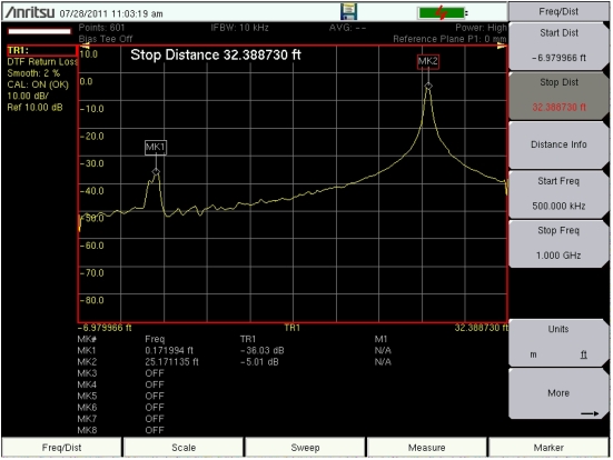
The example in this figure may not match the display on your instrument.
DTF Measurement With a 20 dB Attenuator at MK1 and an Antenna at Cable End
DTF Measurement Calculations
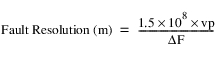
Fault Resolution
Fault resolution is the ability of the system to separate two closely spaced discontinuities. If the fault resolution is 10 feet and two faults are 5 feet apart, then the VNA Master will not be able to show both faults unless Fault Resolution is improved by widening the frequency span.
DMax
DMax is the maximum horizontal distance that can be analyzed. The Stop Distance can not exceed Dmax. If the cable is longer than Dmax, then Dmax needs to be improved by increasing the number of datapoints or by lowering the frequency span (ΔF). Note that the datapoints can be set from 1 to 4001.
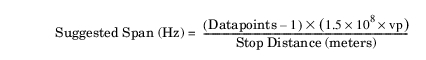
Suggested Span
If the frequency span is set to the suggested span, the Stop Distance will equal Dmax giving the best fault resolution for the given conditions. With Stop Dist entered in meters, the following relationship can be obtained: