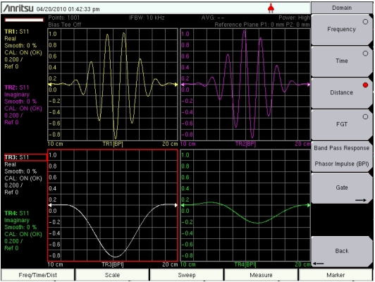
Impedance discontinuities are more difficult to analyze in the time domain with bandpass processing because the phase of the discontinuity cannot easily be extrapolated to DC. A technique called phasor impulse allows you to determine whether a mismatch is caused by a low impedance line or a high impedance line by using a special technique to “unwrap” the phase by using the peak reflection as the starting point. Phasor impulse is available in the Bandpass Mode menu. The graph in the lower‑left corner of
Figure: Phasor Impulse Revealing a Low Impedance Mismatch uses phasor impulse to reveal a low impedance mismatch in a waveguide measurement.
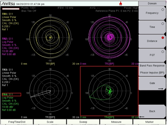
Phasor impulse can also be viewed in a polar plot, as shown in
Figure: Polar Phasor Impulse Revealing a Low Impedance Mismatch. The lower plots use phasor impulse to show a clear reflection with approximately 180 degrees phase, indicating a low‑impedance mismatch. The upper plots use standard bandpass mode and do not adequately reveal the phase of the reflection.