For many phase-sensitive applications, absolute phase shift of a cable is not as critical as the phase matching among multiple cables. For this application, the Vector Network Analyzer relative phase measurement is preferred.
The operations for relative measurements are described in the following steps.
1. From the CW menu, preset the Vector Voltmeter for relative (by an amount) measurements by pressing the Clear Reference soft key.
2. Connect the first DUT (device under test).
3. Save the measurement result of the first DUT by pressing the Save New Reference soft key.
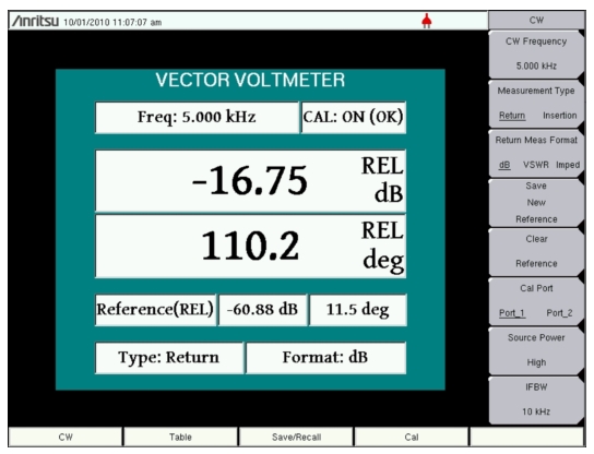
4. As shown in Figure: Continuous Wave Menu with Relative Measurements – MS20xxC VNA Master, the Vector Voltmeter saves the current measurement in a new reference window and converts the main measurement window to display the difference between the current measurement and the saved reference. In other words, saving a reference will normalize the results to the current measurement. When relative measurements are displayed, REL is indicated in the main measurement window.
Continuous Wave Menu with Relative Measurements – MS20xxC VNA Master
5. Connect the second DUT and view the difference between the first and second DUT measurements.
6. To create a new reference, press the Clear Reference soft key followed by the Save New Reference soft key
This completes the procedure for relative measurements.
Measurements Using Comparison Table Display
The Vector Voltmeter procedure includes a convenient table display for comparing up to twelve cables. With this feature, the user can save the first cable measurement as a reference, can view the differences among the other cables, and can output a final report showing both absolute and relative values of all the cables. The following steps describe an overview of the procedure for using this feature.
1. Press the Table function hard key.
2. The setup procedure, including calibration, is the same as Step 4 through Step 9. in the procedure described in section Simple Measurement Using CW Display. Specify CW Frequency and perform the appropriate 1‑port or 2‑port calibration.
3. After calibration, press the Table function hard key.
4. Preset the Vector Voltmeter Mode for relative measurements by pressing the Clear Reference soft key.
6. Save the measurement result of the first DUT by pressing the Save New Reference soft key.
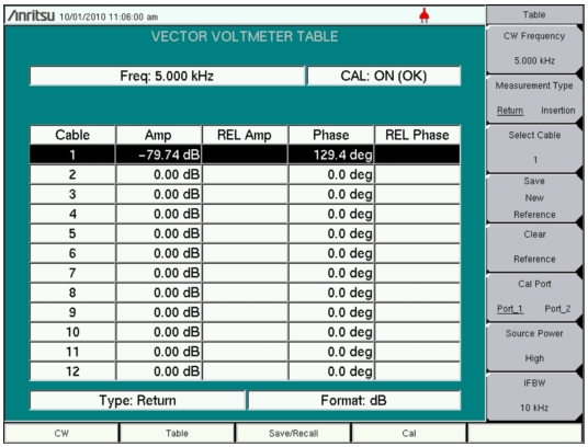
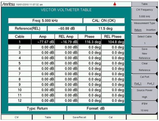
7. As shown in Figure: Vector Voltmeter Relative Measurement Table – MS20xxC VNA Master, the Vector Network Analyzer saves the current measurement in a new reference window above the table and updates the REL Amp and REL Phase columns to display the difference between the current measurement and the saved reference measurement.
8. Before disconnecting the first DUT, save the results in the current row by using the Select Cable soft key to move to another row in the table. When selecting a new cable, the Vector Network Analyzer saves the results and updates measurements for the next cable in the table.
Note
Be sure to keep the DUT connected until a new cable has been selected in order to ensure that the proper values are saved in the table for the final report.
9. Connect the second DUT and view the difference between the first and second DUT measurements. Be careful to avoid selecting another cable when you are done with the measurement. Saved data can be overwritten.
10. To create a new reference, press the Clear Reference soft key followed by the Save New Reference soft key. Consider the possibility of changing the reference by using Select Cable to choose cable 1 again.
This completes the procedure for relative measurements using the table display.