 |
|
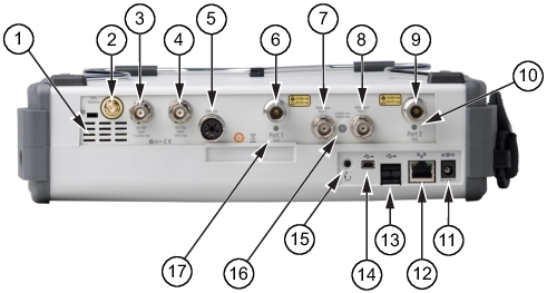 | |
1 | Fan Exhaust Port |
2 | GPS Antenna Input for Option 31 |
3 | External Reference Input |
4 | External Trigger Input |
5 | RF Detector Interface (for Option 5) |
6 | Test Port 1 (50 ohm) The corresponding LED turns green when the port is transmitting. |
7 | Bias Input Port 1 |
8 | Bias Input Port 2 |
9 | Test Port 2 (50 ohm) The corresponding LED turns green when the port is transmitting. |
10 | Port 2 LED |
11 | External Power Input |
12 | LAN Connection |
13 | USB Interface, Type A (2 connectors, Full Speed USB 2.0) |
14 | USB Interface, Type Mini‑B (Full Speed USB 2.0) |
15 | Headset Jack |
16 | Bias Status LED |
17 | Port 1 LED |
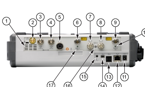 | |
1 | External Reference Input |
2 | Fan Exhaust Port |
3 | Reference Out (10 MHz) |
4 | Spectrum Analyzer RF Input (50 ohm) |
5 | Test Port 1 (50 ohm) The corresponding LED turns green when the port is transmitting. |
6 | Bias Input Port 1 |
7 | Bias Input Port 2 |
8 | Test Port 2 (50 ohm) The corresponding LED turns green when the port is transmitting. |
9 | Port 2 LED |
10 | External Power Input |
11 | LAN Connection |
12 | USB Interface, Type A (2 connectors, Full Speed USB 2.0) |
13 | USB Interface, Type Mini‑B (Full Speed USB 2.0) |
14 | Headset Jack |
15 | Bias Status LED |
16 | Port 1 LED |
17 | GPS Antenna Input for Option 31 |
18 | External Trigger Input |
 |
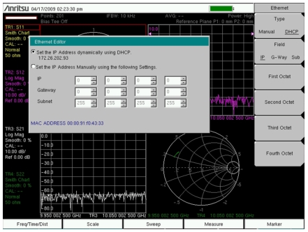
Note | An active Ethernet cable must be connected to the MS20xxC before it is turned ON in order to enable the Ethernet port for DHCP or for a static IP address. Depending upon local conditions, the port may remain enabled when changing from DHCP to static IP address, when changing from static IP address to DHCP, or when temporarily disconnecting the Ethernet cable. If the port becomes disabled, then ensure that an active Ethernet cable is attached to the MS20xxC before cycling the power OFF and back ON. |
Note | In order to acquire an address from a DHCP protocol network, the VNA Master MUST be connected to the network BEFORE being switched on. |
 |
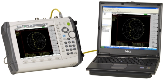
Note | For proper detection, either Line Sweep Tools or Web Remote Tools must be installed on the PC prior to connecting the VNA Master to the PC USB port. |
 |
Note | For proper operation with the instrument, USB Flash Drives should be formatted using either FAT (for drives that are 2GB or less) or FAT32. USB drives with NTFS formatting may not be correctly recognized by the instruments. |