The following description uses Sd1d1 as an example. The same measurements can be made on any of the other parameters: Sc1c1, Sc1d1, or Sd1c1.
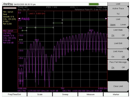
The differential match, or Sd1d1, can be viewed in the frequency domain. It represents the reflections from the differential port of the device under test. Figure: Differential S11 Log Magnitude Display of Sd1d1 shows the Log Magnitude display of Sd1d1 (essentially the return loss) of a differential cable. A segmented limit line with pass/fail alarm is used to verify that this cable meets its specifications.
Differential S11 Log Magnitude Display of Sd1d1
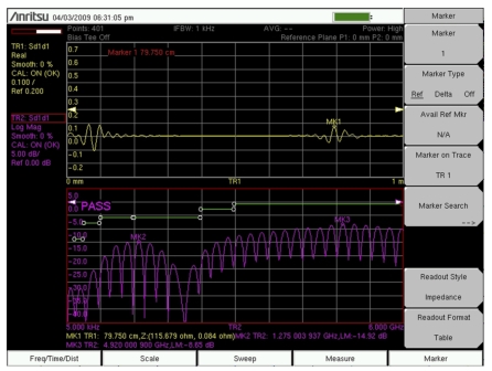
In addition to looking at the frequency response of Sd1d1, the VNA Master (when equipped with Option 2) can display the time or distance domain response (or both) of Sd1d1. This powerful display allows you to check for impedance discontinuities on the differential line.
Frequency and Distance Domain Responses of Differential Cable
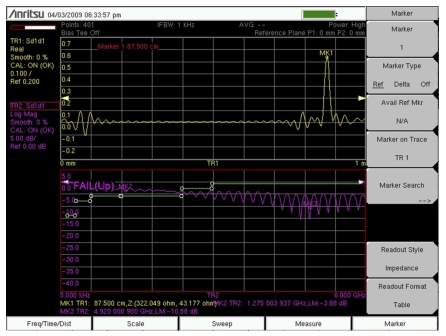
Figure: Cable with Failing Return Loss (Marker Text Size = Regular) shows a cable that fails its return loss specification limits. Looking at the distance domain plot, you can see that the cable has a large mismatch at the end of the cable. The marker reading validates this by providing the impedance value at the end of the cable. In this case, the results point to an open condition at the end of the cable. With its flexible, yet powerful display, and with marker and limits capabilities, the Vector Network Analyzer is able to test differential cables against their specifications, and also it is able to troubleshoot any failures that are identified.
Cable with Failing Return Loss (Marker Text Size = Regular)
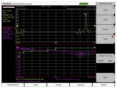
Cable with Failing Return Loss (Marker Text Size = Small)