For the internal function, the bias arm is connected to an internal power source that can be turned on as needed to place the voltage on the center conductor of VNA Port 2 for the MS20xxB or the S412E or on either of the VNA ports for the MS20xxC. Because the MS20xxC features full S‑parameter testing at both Port 1 and Port 2, the bias voltage for these models is also available from either port upon selection by the user. This voltage can be used to provide power to block down‑converters in satellite receivers and can be used to power some tower‑mounted amplifiers.
The bias can be turned on only when the instrument is in vector network analyzer mode and when the lowest frequency is set greater than or equal to 2 MHz. Below 2 MHz, both internal and external bias tee are not supported. When bias is turned on, the LED indicator on the MS20xxC connector panel turns green, and the actual bias voltage and current are displayed in the upper left corner of the measurement display screen. The display shows the voltage and current for the selected port when using internal bias tee, and for both ports when using external bias tee.
Caution
Depending on the load that is presented by the device under test, the bias voltage value that is displayed on the screen may be different than the value that was set using the soft key menu. The value that is displayed on the screen is the actual measured value of the voltage that is being delivered to the device under test.
The internal bias tee is designed to continuously deliver a maximum of 450 mA between 12 VDC and 32 VDC in steps of 0.1 V.
Warning
When using external bias tee on MS20xxC models, a maximum of ± 50 VDC at 500 mA is supported.
The ability to provide DC bias voltage at the RF port is an important feature of a VNA. The architecture of the VNA Master, when equipped with Option 10, allows for internal and external bias at both RF ports.
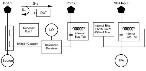
Figure: Internal Bias (MS20xxB and S412E shown) shows how the MS20xxB and the S412E can provide an internal voltage between 12 volts and 32 volts that is applied to the center conductor of VNA Port 2 or of the RF In port (SPA Input). That voltage would be available at the port along with the RF signals.
Internal Bias (MS20xxB and S412E shown)
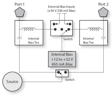
Figure: Internal or External Bias (MS20xxC shown) shows how the MS20xxC can provide an internal voltage between 12 volts and 32 volts that can be switched between Port 1 and Port 2. That voltage would be available at the port along with the RF signals. Alternatively, an external voltage source could be connected to the Bias Tee input ports in order to provide a bias voltage between + 50 volts and – 50 volts at both ports simultaneously, if desired.
Internal or External Bias (MS20xxC shown)
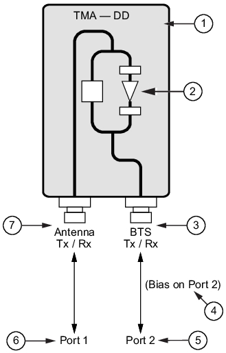
Variable Bias Tee on TMA‑DD
1
TMA – DD (Tower Mounted Amplifier – Dual Duplex)
2
Internal Components
3
Base Station Transmit and Receive Connection
4
Bias voltage is on Port 2
5
Port 2 of VNA Master
6
Port 1 of VNA Master
7
Antenna Transmit and Receive Connection
Figure: Variable Bias Tee on TMA‑DD shows a variable bias tee supplying bias power out of Port 2 to the test unit, which is a dual duplex tower‑mounted amplifier.