Many menus display limited soft key functionality in Field view. Various keys that are available in VNA measurements view may be in different locations or may not be displayed at all. Refer to Field View Menus and VNA View Menus.
VNA Measurements
The following sections provide detailed descriptions of the various Vector Network Analyzer measurements. Some of these measurements can be displayed in either Field measurements view or VNA measurements view. The following procedures describe only the Field measurements view.
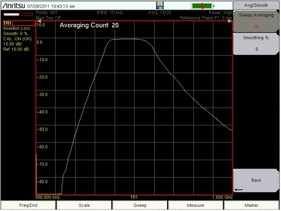
Sweep averaging can be calculated by a variable number of sweeps. In the Sweep menu, press the Avg/Smooth soft key to open the Avg/Smooth menu. In this menu, you can also set the smoothing percentage from 0 % to 20 %. To set the number of sweeps that are used to calculate sweep averaging, press the Sweep Averaging soft key and enter a number. Figure: Display Type Single – Insertion Loss with Sweep Averaging Set to 20 shows a trace with Sweep Averaging set to 20 sweeps. The example in this figure may not match the display on your instrument.
Display Type Single – Insertion Loss with Sweep Averaging Set to 20
Return Loss/VSWR
Return Loss is used to characterize RF components and systems. The Return Loss indicates how well the system is matched by taking the ratio of the reflected signal to the incident signal, measuring the reflected power in dB. The 1‑port Measurement data can also be displayed linearly as VSWR. In addition, this information can be transferred to a PC for additional analysis by using Master Software Tools.
Procedure
1. If a test port extension cable is to be used, then connect it to the VNA Port 1 connector on the instrument.
2. Ensure that the instrument is in Vector Network Analyzer mode. Then press the Shift key and the System (8) key.
3. Press the Application Options soft key. The Meas Menu soft key toggles between Field and VNA. The active measurement function is underlined.
Press the soft key (if necessary) until Field is underlined. The Measure menu now displays Field measurement functions.
4. Press the Measure function hard key (main menu key).
5. Pres the Display Type soft key (submenu key) and select Single from the list box.
6. Press the Measurement Type soft key. From the Graph Type Selector list box, select Return Loss.
7. Press the Freq/Dist function hard key and set the Start Frequency and Stop Frequency.
8. Press the Sweep function hard key and then the Data Points soft key to set the number of data points (the larger the number of data points, the longer the maximum distance, at the expense of a slower sweep speed).
9. Press the Shift key, then the Calibrate (2) key.
10. Press the Start Cal soft key and perform a 1‑port calibration at the connector or at end of the extension cable. Follow the instructions on the display or, for more details, refer to Calibration Considerations.
11. When the Calibration is finished, CAL: ON (OK) should be displayed with the trace data in the instrument settings summary at the left side of the sweep window, and the trace should be centered around 0 dB when the short or open is connected.
12. Connect the test port extension cable to the Device Under Test (DUT).
13. Use the File menu to save the measurement. Refer to the file management instructions in the user guide for your instrument.
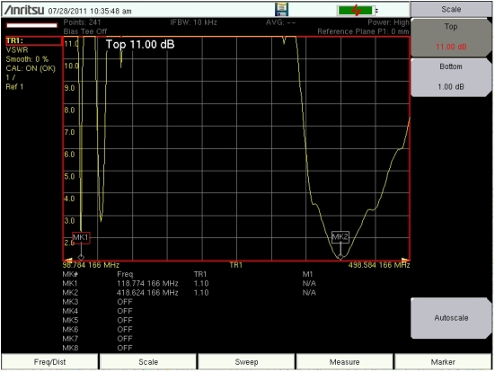
14. Press the Measure function hard key and select VSWR from the Graph Type Selector list box to view the match in VSWR. Figure: Display Type Single – VSWR Measurement is displaying a VSWR measurement and the Measure menu of the Field setting when Display Type is Single. The example in this figure may not match the display on your instrument..
Display Type Single – VSWR Measurement
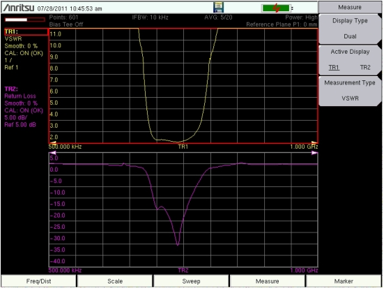
Figure: Display Type Dual – VSWR and Return Loss is displaying both a VSWR measurement and a Return Loss measurement. Note that the Measure menu of the Field setting shows Display Type is Dual. and that the Active Display soft key provides for selection of TR1 or TR2.
Note
On instruments with a touch screen, you may tap a measurement trace or the trace data in the Instrument Settings Summary to make a trace the active trace.
The example in this figure may not match the display on your instrument.