The MS20xxB VNA Master or the S412E LMR Master can display both Return Loss and Insertion Loss phase measurements. 2‑Port Phase measurements can use power settings of High (0 dBm), Default (–5 dBm), and Low (– 25 dBm).
1‑Port Phase Measurement
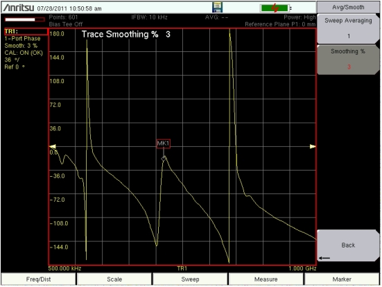
The following example compares the phase of two cables using a 1‑port phase measurement. The dynamic range and phase uncertainty are better with 2‑port phase measurements. Figure: Return Loss, 1‑Port Phase Measurement shows a typical 1‑Port Phase measurement (Return Loss). This screen display may not match the display on your instrument.
Procedure
1. Press the Measure function hard key and then press the Measurement Type soft key and select 1‑Port Phase.
2. Press the Freq/Dist function hard key and set the Start Frequency and Stop Frequency.
3. Press the Sweep function hard key and then the Data Points soft key to set the number of data points (the larger the number of data points, the longer the maximum distance, at the expense of a slower sweep speed).
4. Press the Shift key, then the Calibrate (2) key.
5. Press the Start Cal soft key and perform a 1‑port OSL calibration at the desired reference plane (VNA Port 1 connector or end of test port cable).
6. When the Calibration is finished, CAL: ON (OK) should be displayed with the trace data in the instrument settings summary at the left side of the sweep window, and the trace should be centered around 0 dB when the short or open is connected.
7. Connect Cable A to VNA Port 1 reference plane (or to the end of the test port cable).
8. Press the Shift key, then the Trace (5) key.
9. Press the Save Trace to Memory soft key.
10. Remove Cable A and connect Cable B to VNA Port 1 reference plane (or to the end of the test port cable).
11. Press Shift and then Trace (5) to display the Trace menu. Then press Trace Math.
12. Press the Trace Minus Memory soft key to view the difference in phase between the two cables.
13. Use the File menu to save the measurement. Refer to the file management instructions in the user guide for your instrument.
The example in this figure may not match the display on your instrument.
Return Loss, 1‑Port Phase Measurement
2‑Port Phase Measurement
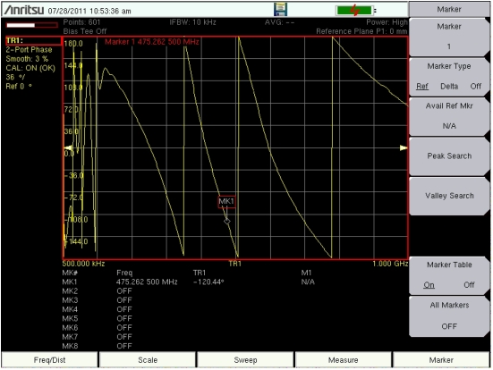
The following example compares the phase of two cables using a 2‑port phase measurement. Figure: Insertion Loss, 2‑Port Phase Measurement shows a typical 2‑Port Phase measurement (Insertion Loss). This screen display may not match the display on your instrument.
Procedure
1. Press the Measure function hard key and then press the Measurement Type soft key and select 2‑Port Phase.
2. Press the Freq/Dist function hard key and set the Start Frequency and Stop Frequency.
3. Press the Sweep function hard key and then the Data Points soft key to set the number of data points (the larger the number of data points, the longer the maximum distance, at the expense of a slower sweep speed).
4. Press the Shift key, then the Calibrate (2) key.
5. Press the Start Cal soft key and perform a 2-port OSL calibration at VNA Port 1 and VNA Port 2.
6. When the Calibration is finished, CAL: ON (OK) should be displayed with the trace data in the instrument settings summary at the left side of the sweep window, and the trace should be centered around 0 dB when the short or open is connected.
7. Connect Cable A (the reference cable) between the VNA Port 1 and VNA Port 2 connectors.
8. Press the Shift key, then the Trace (5) key.
9. Select the Save Trace to Memory soft key.
10. Remove Cable A, and connect Cable B (the cable under evaluation).
11. Press Shift and then Trace (5) to display the Trace menu. Then press Trace Math.
12. Press the Trace Minus Memory soft key to view the difference in phase between the two cables.
13. Use the File menu to save the measurement. Refer to the file management instructions in the user guide for your instrument.
The example in this figure may not match the display on your instrument.