To help you with the time and distance setup, the VNA Master provides a helpful aid that provides information on the resolution and maximum range.
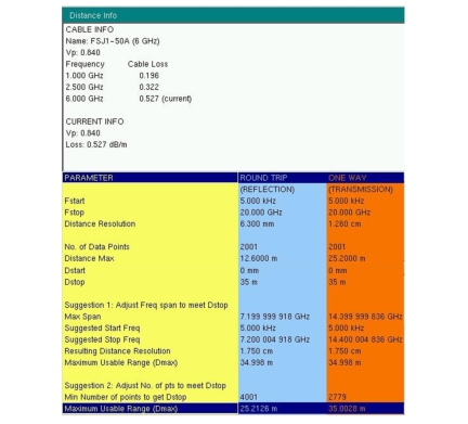
Figure: Distance Info Window shows the Distance Info window (which can be displayed from the Additional Dist Setup submenu under the Distance Setup menu). This window provides information to help you with the distance domain setup. The top portion of the window displays information about the selected Cable or Waveguide. If you select a cable from the cable list (or a waveguide from the waveguide list), then the name of the cable and its associated parameters are displayed under the heading CABLE INFO (or WAVEGUIDE INFO). Below that heading is the CURRENT INFO section, which summarizes the actual parameters being used in the measurements. For cables, the parameters are propagation velocity and cable loss. For waveguide, they are cut‑off frequency and waveguide loss. These current parameters are either the values that are associated with the chosen cable or waveguide from the list, or they are the values that are entered directly by the user.
The bottom part of the list provides information about the settings and suggestions for meeting the maximum required distance. This section is divided into three columns, headed: PARAMETER, ROUND TRIP, and ONE WAY for one‑way measurements. They key parameters that are displayed are the Distance Resolution and the Distance Max. The following list includes all of the items in the Distance Info window with a brief description of each item:
Fstart
the start frequency
Fstop
the stop frequency
Distance Resolution
the calculated distance resolution based on the frequency range
No. of Data Points
number of points in the sweep
Distance Max
maximum usable distance based on frequency span and number of points
Dstart
the start distance
Dstop
the stop distance (when set greater than Dmax, the following suggestions can be used to increase Dmax to make it equal to Dstop)
Suggestion 1
Adjust Freq span to meet Dstop
Max Span
suggested frequency span (within allowable range) to make Dmax = Dstop
Suggested Start Freq
typically equal to the Fstart that was set by user
Suggested Stop Freq
suggested stop frequency based on calculated Max Span and Fstart
Resulting Distance Resolution
resulting resolution if new Fstart and Fstop are used
Maximum Usable Range (Dmax)
resulting Dmax if new Fstart and Fstop are used
Suggestion 2
Adjust No. of pts to meet Dstop (using current Fstart and Fstop)
Min Number of points to get Dstop
suggested number of points to make Dmax = Dstop
Maximum Usable Range (Dmax)
resulting Dmax if the new number of points are used
Distance Info Window
Note
As you can see in Figure: Distance Info Window, the user has entered a Dstop value of 35 m, whereas the calculated maximum usable range (Distance max) is 12.6 m for a reflection measurement and is 25.2 m for a transmission measurement. As the user, you need to make some adjustments either to the frequency range or to the number of data points in order to increase Dmax to 35 m. Suggestion 1 (of the Distance Info) tells you that you need to reduce your frequency span to 7.199 GHz (14.399 GHz for transmission). You can do that by changing just the stop frequency, or you can change both the start and stop frequencies such that the difference between them equals the calculated Max Span. By making that adjustment, you can achieve a Dmax of 35 m. What you give up is distance resolution. In the example in Figure: Distance Info Window, the resolution will degrade to 17.5 mm. To avoid changing the frequency span (and thereby degrading the resolution), you can increase the number of points (at the expense of slower sweep speed). In the example in Figure: Distance Info Window, however, even if you increase the number of points to the maximum allowable number of 4001 (for reflection), you can achieve only a Dmax of 25.2 m. For a transmission measurement, 2779 points will let you achieve 35 m. In this case, you should either use a transmission measurement or adjust the frequency span to meet your goal.
The Time Info window does not contain any cable or waveguide information because those parameters affect only the distance setup. Also, in the Time Info window, the two columns for round trip and one way are identical because the time domain has no round trip compensation.