Another popular 2-port device is the amplifier. For amplifier measurements, configuring the instrument to low power mode is an important step. This reduces the source power to ensure that the amplifier and the VNA Master (or LMR Master) do not go into compression. The screen‑captured measurements that are shown in this measurement guide are examples and may not match any display on your instrument.
Setup Considerations
To measure the amplifier, set source power to low and perform a full 2-port calibration by using the appropriate connector type. Connect the amplifier between the test ports, and bias the amplifier. The VNA Master offers both internal and external test port bias supplies. These can be utilized to power devices that accept bias through their test ports. Also refer to section Calibration Considerations.
Measurement Readout and Interpretation
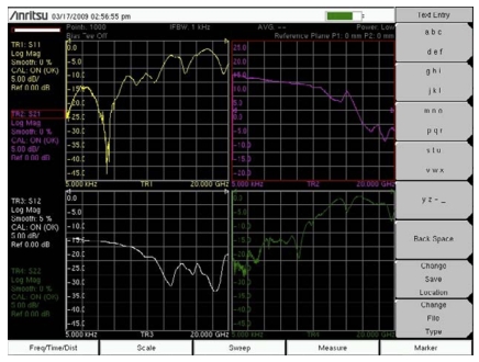
The screen‑captured measurement that is illustrated in Figure: Gain, Input Match, Output Match, Isolation of an Amplifier shows gain (S21 = TR2), input match (S11 = TR1), output match (S22 = TR4), and isolation (S12 = TR3)) of an amplifier all at the same time on different graphs.
Gain, Input Match, Output Match, Isolation of an Amplifier
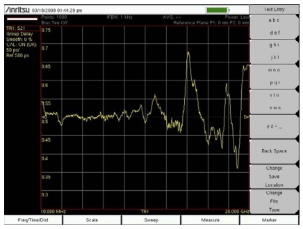
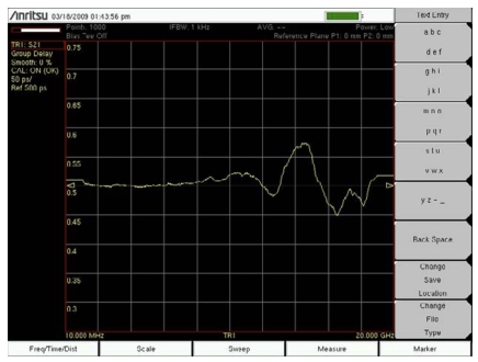
Group delay is another popular measurement with broadband amplifiers. The two plots that are illustrated in Figure: 2 % Aperture and Figure: 10 % Aperture show the group delay of the amplifier with 2 % aperture and 10 % aperture. Increasing the group delay aperture makes the measurement less susceptible to noise, but provides less fine detail in phase linearity.
2 % Aperture
10 % Aperture
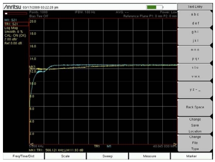
The 5 kHz low end of the MS20xxC VNA Master facilitates the characterization of low frequency resonances that are commonly caused by bias networks. The screen‑captured measurement that is illustrated in Figure: Proper Biasing versus Defective Bias Inductor shows the difference between an amplifier with proper low frequency biasing (TR1) and one with a defective bias inductor (M1).