Only the MS20xxC VNA Master models accommodates waveguide measurements in addition to the previously discussed coaxial measurements.
Setup Considerations
The primary difference between waveguide and coax measurements is the calibration. Coax is typically calibrated by using an open, short, load, and through line. Waveguide calibration components do not include an open because the open end of a waveguide is actually an effective radiator and does not reflect much of the signal back to the test port. Offset shorts are typically used to replace the open. Short, offset‑Short, Load, Through (SSLT) is a common waveguide calibration that is supported by the VNA Master. Triple offset short (SSST) is another calibration option. Because this calibration avoids having a load standard, it can lead to better ultimate directivity. It is, however, more band‑limited and is more susceptible to wear on the calibration components. Also refer to section Calibration Considerations.
Measurement Readout and Interpretation
In the Distance Domain, the VNA Master includes waveguide dispersion correction to account for different propagation speeds of signals in the waveguide. Dispersion correction is not applied in Time Domain. The S11 measurement of a 15 cm shorted waveguide section (Figure: S11 on 15 cm Shorted Waveguide Section) shows how dispersion compensation improves distance domain resolution.
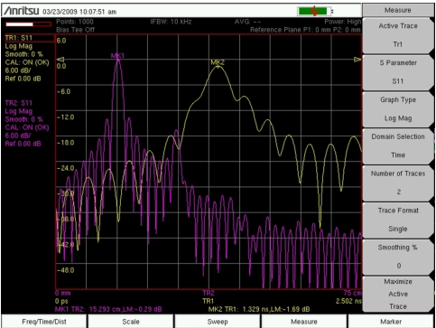
S11 on 15 cm Shorted Waveguide Section
Trace TR1 (yellow trace) is in the time domain without dispersion correction. Trace TR2 (purple trace) is in the distance domain. Peaks and troughs are better defined in the distance domain (TR2) than in the time domain (TR1). Note that the distance domain response is shown as One‑Way, whereas the time domain plot is shown as Round‑Trip.
Both traces begin at the low end of the frequency range at approximately – 35 dB.
TR1 (time domain) peaks at 1.329 ns and – 1.69 dB as shown by Marker MK2. TR2 (distance domain) peaks at 15.293 cm and – 0.29 dB as shown by Marker MK1.
Note
When measuring reflection parameters (such as S11 in the Figure: S11 on 15 cm Shorted Waveguide Section example), the distance domain measurement is adjusted so that the peak of the signal is at the end of the cable or waveguide (a length of 15 cm in the example). This is called a One‑Way representation of the measurement. The signal itself travels round‑trip to the end of the cable and then back to the port.
If the VNA Master does not adjust for the round-trip condition, then the peak of the signal will be at a distance that is twice the length of the cable (in which case, the measurement would have been called Round‑Trip).
In the time domain, you can choose to set the reflection measurement to be either One-Way or Round-Trip. When set to One-Way (which is the default setting), the VNA Master compensates for the round trip reflection measurement as it does in the Distance Domain. When set to Round‑Trip, the VNA Master does not compensate, and the peak of the signal in the time domain therefore represents the time that is taken for the signal to reach the end of the cable and reflect back to the port (1.3 ns in the Figure: S11 on 15 cm Shorted Waveguide Section example).