 | |
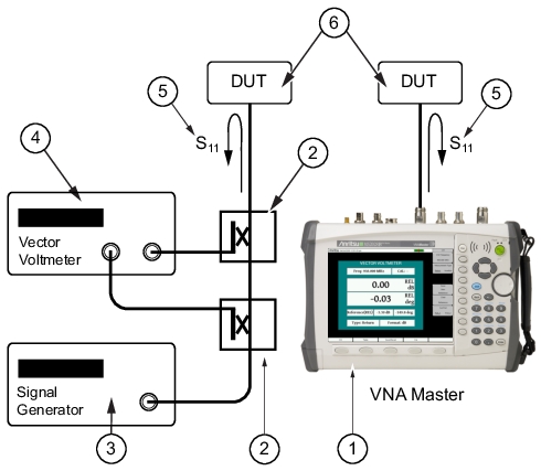
1 | VNA Master |
2 | Couplers |
3 | Signal Generator |
4 | Vector Voltmeter |
5 | S11 Reflection Measurement |
6 | DUT (Device Under Test) |
| |
1 | VNA Master |
2 | Couplers |
3 | Signal Generator |
4 | Vector Voltmeter |
5 | S11 Reflection Measurement |
6 | DUT (Device Under Test) |
Note | Disclaimer (an important distinction): The Vector Voltmeter Option 15 in the Anritsu VNA Master and LMR Master does not measure RF voltages. The traditional vector voltmeter function of probing RF voltages (A and B) in two channels, and displaying A, B, A/B, B/A, and the phase difference between them is now obsolete, and those instruments are no longer available. The Vector Network Analyzer has replaced the ratio functions of the vector voltmeters. The Vector Network Analyzer measures those amplitude and phase ratios very accurately. Thus it is a suitable replacement for the most used ratio function of VVMs, that of measuring component parameters. |