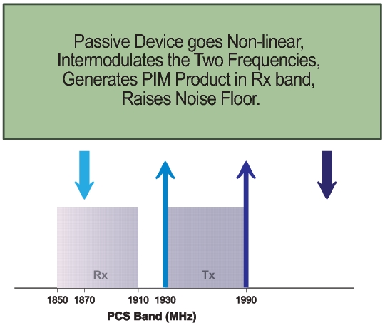
PIM is a form of intermodulation distortion that occurs in passive components normally thought of as linear, such as filters, combiners, surge protectors, cables, connectors, and antennas. When subject to the high RF powers found in cellular systems, however, these devices can generate spurious signals.
PIM shows up as a set of unwanted signals created by the mixing of two or more strong RF signals in a non‑linear device, such as in a loose or corroded connector, or in nearby rust. Other names for PIM include the “diode effect” and the “rusty bolt effect”.
Many symptoms could be indicators of PIM problems, which include the following:
• Receiver desensitization (raised noise floor)
• Rx Diversity alarms
• Spectral regrowth in the transmitter mask
• Excessive dropped or blocked calls, or both
• Cell site coverage shrinking
• Complaints of interference from neighboring cell site owners
PIM signals in the cell receive band can raise the receive noise floor, increase the bit error rate, and shrink the reception area for cellular communications. PIM can come from junctions; from improperly tightened, damaged, or corroded connectors; from filters, combiners, and surge protectors; and from damaged antennas. Other sources include rusty components, such as mounts and bolts or nearby metal structures.
Power in dBm and dBc
A measurement reading in dBm is absolute power. A measurement value with units of dBc is relative power.
For example, if you set TX1 and TX2 to 43 dBm and get a measurement result of –120 dBm (the measurement result as absolute power), this represents a relative power of –163 dBc. The calculation is as follows:
–120 dBm – 43 dBm = –163 dBc
[measured power in dBm] minus [transmitted power in dBm]
equals [relative power in dBc]
The term relative power, in this example, is referring to the original output power setting of 43 dBm. When stated in units of dBc, the received PIM power is relative to (is being compared to) the transmitted power level of one test tone. The difference between the transmitted power (in dBm) and the measured PIM power (in dBm) is the relative power, which is then expressed in units of dBc. This is not applicable in Noise Floor measurements.
Why Test for PIM?
The PIM Master is an integrated source and receiver that generates a high‑power signal that excites micro arching and PIM. These signals are picked up by the on‑board receiver.
Anritsu has developed the PIM Master to verify and troubleshoot Passive Intermodulation (PIM). The PIM Master generates two high‑power tones, usually in the transmit band of interest. It displays and measures the third‑order, fifth‑order, or seventh‑order intermodulation products returning from the DUT to the PIM Master. (The third, fifth, and seventh‑order intermodulation products can be measured only if they fall into the range of the receive band.) In addition, the PIM Master can measure the Distance‑to‑PIM of multiple PIM sources, which provides the distance to the source and its relative magnitude, both inside the antenna system and beyond.
The current standard of PIM testing utilizes this system of two primary carriers and a calculated third‑order PIM frequency. This provides a measurement of the overall linearity of the antenna system and the surrounding environment. A formula for determining third order intermodulation (IM3) frequencies is provided in section Intermodulation Distortion.
When more carriers are added to a site and transmit power is increased, the impact of PIM on site performance becomes more severe. Traffic through the site plays a big part. A relatively quiet site will not usually exhibit the same performance problems as a busy site.
Line Sweeping and PIM testing
Line Sweep testing and PIM testing are very different tests. Both are very important and accurate measures of the ability of the cell site to provide service and to perform optimally.
PIM testing measurements reflect the overall linearity of an antenna feed line, the antenna, and the area illuminated by the transmitted signal. The Line Sweep measurements reflect the overall impedance matching of all of the components in an antenna feed line. Both tests need to be performed in order to ensure the overall quality on a site.
PIM testing requires both low system loss and good return loss (VSWR) if the PIM testing is to be performed to an acceptable standard. If PIM testing is performed prior to line sweep testing, then you may not be aware of the impedance characteristics of the transmission line. High insertion loss attenuates the PIM test signals, which prevents the high power characteristics from reaching the specific components that require stringent PIM testing. Poor return loss reflects a percentage of the PIM test signals back into the test set, which causes some signal cancellation that can report a false pass. In other words, poor line sweep performance can lead to a false pass for a PIM test.
By performing the line sweep test prior to PIM testing, you can be confident the insertion loss and return loss data are at acceptable levels. This data in turn ensures that the PIM test signals actually reach the components at the highest possible signal level, offering the most accurate indicator of true PIM performance. By constructing a system using modern low PIM practices, the need to break the transmission system back open will be minimized. If the lines are disassembled again to repair or clean a connector, the line sweep and PIM testing will need to be repeated.
Causes of PIM
PIM is caused by two or more strong RF signals mixing in a non‑linear device. These non‑linear devices, or junctions, occur in improperly tightened, damaged, or corroded connectors or in damaged antennas. Rusty components, such as mounts and bolts, are also suspect when hunting for sources of PIM.
Many common frequency combinations can produce PIM products that fall in a cell receive band. PIM signals in the cell receive band have the following effects:
• Raise the receive noise floor
• Increase the bit error rate
• Decrease the coverage area
• Cause early handoff
• Increase dropped calls
• Increase early termination
• Require the mobiles in the cell to increase Tx power (increasing battery drain)
Proper care and maintenance of connectors is essential to keeping PIM low. Inspection and cleaning is a central part of good performance. Proper torque is important, because the seals and interface areas are designed for this pressure.
PIM Testing Example
PCS Band PIM Testing
Intermodulation Distortion
The intermodulation distortion (IMx) is a mathematical function of F1 and F2.
3rd Order Intermodulation (IM3) = 2F1 – F2 or (IM3) = 2F2 – F1