PIM Master™ Passive Intermodulation Analyzer : PIM Master Overview : Hardware Overview
  
Hardware Overview
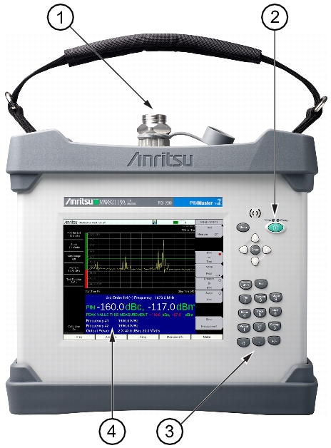
The PIM Master is a handheld, battery‑operated PIM analyzer with a touch screen user interface. The RF output connector is on the top panel, and all other connectors are located behind a cover on the side panel. The battery compartment is on the bottom. Refer to Battery Care for battery care and Battery Replacement for battery replacement instructions.
Accessory items such as a PIM standard, Low PIM termination, and Low PIM test lead are required in order to calibrate and operate the PIM Master. Accessory items can be purchased together in a kit or individually from Anritsu.
A connector saver reduces wear on the built-in RF Out connector. Refer to Connector Saver.
 
MW82119A PIM Master Front Panel
1.  
RF Out Connector (connector saver attached), 7/16 DIN, female, 50 Ω
2.  
On/Off Button
3.  
Number Keypad
4.  
Measurement Display (a Touch Screen)
 
RF Out Connector
 (item 1 in Figure: MW82119A PIM Master Front Panel)
The PIM Master fits into its soft carrying case and transit case with a 7/16 DIN, female, 50 Ω connector saver attached. Refer to Connector Saver and RF Out Connector.
On/Off Button
 (item 2 in Figure: MW82119A PIM Master Front Panel)
Press to turn On the PIM Master. Press and hold to turn Off the PIM Master.
Number Keypad
 (item 3 in Figure: MW82119A PIM Master Front Panel)
Refer to Number Keypad.
Measurement Display
 (item 4 in Figure: MW82119A PIM Master Front Panel)
Touch Screen information begins in Touch Screen.
Other Features On The Front Panel
Battery Charge LED (Green)
The Battery Charge LED flashes if the battery is charging, and remains on steady when the battery is fully charged.
Power LED (Green)
The Power LED remains on when the PIM Master is on.
Features not shown in Figure: MW82119A PIM Master Front Panel
Battery Compartment
The battery compartment access is on the bottom of the PIM Master. Refer to Battery Replacement.