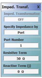
Most VNA calibrations are performed referenced to 50 ohms, as this is usually set by the calibration kit. While some calibration kits exist for other impedances (75 ohm N and F connectors for example), they are not common and a custom impedance may be of interest. The impedance transformation function allows performance of a calibration in one impedance and then transformation of the result to appear as if it had been calibrated in a different impedance. As a crude example, if a 75 ohm N calibration kit is not available, but a 50 ohm kit is, neglecting issues with adapters, the 50 ohm calibration could be performed and the utility used to reference the results to 75 ohms. The IMPED. TRANSF. (IMPEDANCE TRANSFORMATION) menu for this function is shown below (Figure: IMPED. TRANSF. (IMPEDANCE TRANSFORMATION) Menu).
Another application of this function is to correct calibrations for the case where it is found that the actual reference impedance (e.g., the characteristic impedances of lines in LRL/TRL calibrations or the load impedance in LRM and SOLT calibrations) is not ideal. Once the actual impedance of the calibration is known, the impedance transformation tool can be used to convert results to those referenced to 50 ohms (or some other value).
The ports can be set independently by using the Port Number toggle button and can be set to any complex value except 0 (zero). Generally, a non-real value will only have meaning in a narrowed frequency range.
A full-term calibration must be active for impedance transformation to take effect and only those ports currently calibrated will be affected.
IMPED. TRANSF. (IMPEDANCE TRANSFORMATION) Menu
The calculations are based on a pseudo-wave framework (e.g., R. B. Marks and D. F. Williams, “A general waveguide circuit theory,” J. Rsrch. of the Nat. Inst. Of Stds. And Tech., vol. 97, pp. 533-561, Sept-Oct 1992). The equations used are matrix-based (scaling with number of ports) and defined by:
where:
The default is to specify the new reference impedances by port, but it can also be done by port pair. In this case, common-mode and differential impedances (per pair) are specified instead of by single-ended ports. This approach can be useful for certain engineered transmission lines where the single-ended impedances are complex.