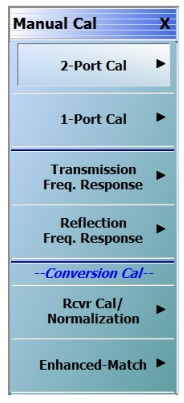
While many of the mixer calibration topics with regard to conversion gain/loss have already been discussed in passing, it may be helpful to review some of their attributes. When a mixer has been set up using the tools described, the manual calibration menu changes to that shown in Figure: The MANUAL CALIBRATION Menu When in Mixer Mode.. The two bottom buttons describe two options
• Rcvr Cal/Normalization: A receiver cal is performed (as part of the ‘thru’ step) to establish absolute power accuracy and then a normalization is done to take into account the power incident on the mixer input port. A separate receiver calibration does not need to be performed. A power calibration is recommended for increased accuracy and this must be executed separately. Ideally, the power calibration would be performed over input and output frequency ranges (using segmented sweep can save time). Note that for mmWave applications, the system should be in the proper leveling mode when the calibration is performed (for example, RF leveling for the 3743x modules).
This calibration is very fast to perform and only one sweep is needed during the measurement, but as will be discussed in the uncertainties section, does become less accurate as the DUT match degrades.
• Enhanced Match: This is the process that was described in Mixer Measurements where match components at the input and output of the mixer are taken into account. This calibration is structured very much like a traditional full 2-port calibration, except several different frequency lists are employed: input range→input range, input range→output range, output range→output range.
The MANUAL CALIBRATION Menu When in Mixer Mode.
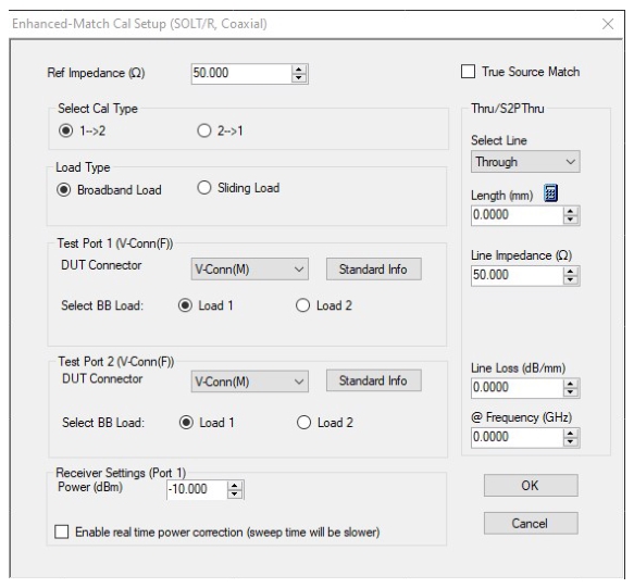
The enhanced match calibration can be performed in any media type and with any of the defined-standards calibration algorithms. An example of the setup dialog is shown in Figure: Example Enhanced Match Cal Setup Dialog. Note that the direction of the calibration is fixed by the input/output relationship defined in mixer setup and reciprocal connections are not available due to the power transfer computation requirement. The True Source Match checkbox was described in Mixer Measurements and refers to a different set of internal calibration steps used, particularly for millimeter wave applications, when a more accurate measurement of the driving match that the DUT sees is needed. This selection will almost never make things worse (one exception being if the driving network is marginally stable when out-of-band due to the addition of an amplifier in the system loops) and can improve conversion loss flatness at higher frequencies.
Example Enhanced Match Cal Setup Dialog
Systems with options 06x will have an 'attenuation' field visible in the lower part of the dialog. Systems in broadband mode will also have a 'Power > 54 GHz' field.
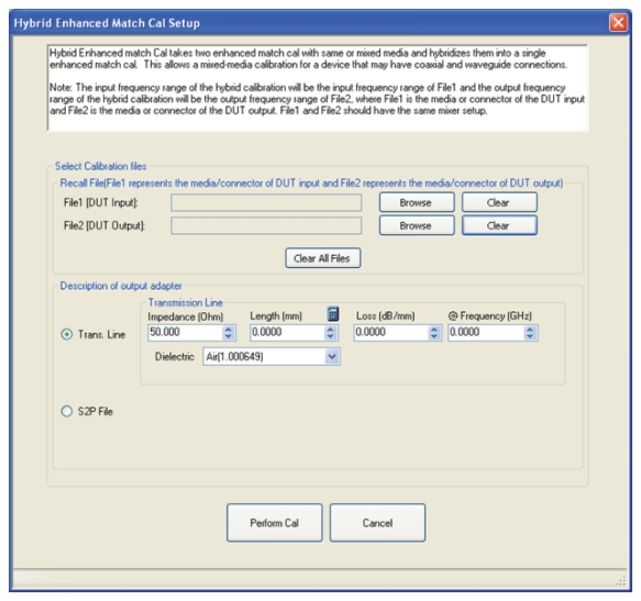
When an enhanced match calibration is being applied, one may note that three sweeps are required. These are used to get DUT input and output match (non-frequency converting measurements in different ranges) as well as conversion. In certain cases, one wishes to perform an enhanced match calibration but the input and output media of the DUT are different (for example, waveguide and coax) and perhaps different algorithms need to be used on those ports (for example, SSLT and SOLT). Analogous to the hybrid calibrations referenced for non-frequency converting measurements earlier in this guide, there is a hybrid enhanced match calibration to handle this case for mixers. The dialog, accessible from the ALTERNATIVE CALS menu (via the CALIBRATION menu, is shown in Figure: Hybrid Enhanced Match Calibration Setup Dialog.
Hybrid Enhanced Match Calibration Setup Dialog
The Hybrid Enhanced match calibration dialog is shown here. This approach is helpful for mixers with different connection media at input and output (such as a waveguide input, but a coaxial output).
The process, again analogous to regular hybrid calibrations, is that one performs an enhanced match cal in each of the media types (and/or algorithm choices), and this utility combines them. The key point is that each calibration is not frequency converting, so the relevant pieces of the calibration for each media type can be extracted to form the hybrid calibration.
Consider an example using the ME7838A/AX broadband system.
• Input 91–95 GHz in WR-10 (will need to use a SSLT calibration kit at this plane)
• Output 1–5 GHz in coax (will use an SOLT calibration kit at this plane)
• LO (not shown) fixed at 90 GHz
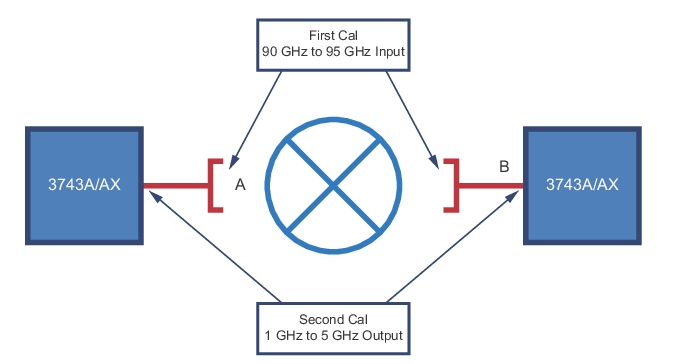
Two complete enhanced match calibrations are completed where the ME7838A/AX system (using 3743A/AX mmWave modules) natively use 1 mm connectors. Coax-to-waveguide adapters are in place for the first enhanced match calibration and are removed for the second. The same mixer frequency plan is used for each calibration. Schematically, the calibration reference planes are as shown in Figure: Example Hybrid Enhanced Match Calibration Setup. We desire the final reference planes to be at A and B.
Example Hybrid Enhanced Match Calibration Setup
During the first (waveguide) calibration, one may notice some data being acquired that is nonsensical since it is below the waveguide cut-off. This ends up being OK since those measurements are not used in the hybrid computation, but leaving them in the execution sequence allows the instrument to relatively easily offer almost all calibration permutations. When the two calibrations are performed and saved, they can be loaded into the dialog of Figure: Hybrid Enhanced Match Calibration Setup Dialog.
The final step is a description of the output adapter, which is needed to get the power calibration transfer as accurate as possible. A simple transmission line model can be used or a .s2p file (covering the input frequency range, preferably) can be entered. In the latter case, interpolation and flat-line extrapolation of the file will be used when the frequency lists do not match. Normally this adapter loss is much less than 1 dB and it does not have a great effect, but there are exceptions based on the user setup.
Another important point is what happens to the conversion results (using either receiver/norm or enhanced match calibrations) when the drive power is changed after calibration. Since the input signal to the DUT is measured during calibration and used to compute conversion gain, there is the potential for confusion if that input power changes later.
In the MODIFY CAL dialog is a power field. This field will specify at which level the receiver calibration portion will be performed. Ideally, this would be at the level where a user power cal had been performed or, if none, at default power. This can now be different from the power where the normalization activities occur which are dictated by the main power menu settings. If there are no changes, both receiver calibration and normalization will happen at default power. For option 06x systems, there is also an 'attenuation' field where the drive side source attenuator can be set for the receiver calibration. For broadband systems, there is an additional field for power > 54 GHz so the power during receiver calibration can be configured by band. This allows the receiver cal and normalization to be decoupled, in terms of power level, which can be important when there are large gain differences in the paths.
Importantly, when the power is now changed after calibration, this system will note the difference relative to the normalization-time power and correct the conversion value by that amount. The correction is only as good as the power calibration (hence a user power calibration can help) since it is simply done on a dB-by-dB basis from the power menu entries.
This correction can be improved upon using the 'real-time power correction' selection. With this mode selected, an extra measurement of the reference receiver power is done at calibration time to establish a baseline. Then, when the calibration is applied, an extra sweep is done on every cycle to measure the reference receiver at the driving frequencies. The difference between the reference receiver measurements, on a point-by-point basis, is then applied to the final result. If the drive power has changed, the reference signal will also change so the compensation should be reasonably accurate. At extreme levels, there may be differences in receiver linearity that could alter the result and if the DUT match is wildly non-linear, there may be some modest coupling changes that could also affect the correction (and would affect the measurement in other ways as well). Also, at extreme levels where the leveling loop goes unlocked, the deviations may become large.
An extra sweep is required on every measurement cycle so there is some measurement time effect to this approach.
Examples
A simple downconverter was measured using both approaches. The input frequency range was 92.5 to 100 GHz and a fixed LO of 102.5 GHz was employed (generated externally so NONE was selected as the LO on the Active Mixer setup interface). The IF thus sweeps backwards from 10 GHz to 2.5 GHz. An ME7838A4X system was employed for the broadband coverage, but this measurement would easily be done with any of the broadband 2 or 4 port systems.
The rcvr/norm calibration will be performed in both cases with the power menu setting at -10 dBm (both frequency ranges) and the receiver calibration settings in the MODIFY CAL dialog will also be set for -10 dBm (no attenuator in play).
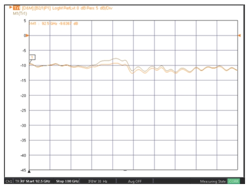
For real-time power correction OFF, the results are shown in Figure: Drive Power Changed After Calibration – Real-time Power Correction Off,when the measurement was done at -10 dBm (brown curve) and when the power menu was then changed to -20 dBm (orange curve). One can see a midband deviation where the ALC calibration linearity was slightly degraded. This is a mm-wave frequency converting measurement, so RF leveling is used, which has less range and linearity than does IF leveling (see Broadband/mmWave Measurements (Option 7, Option 8x) for more information).
Drive Power Changed After Calibration – Real-time Power Correction Off
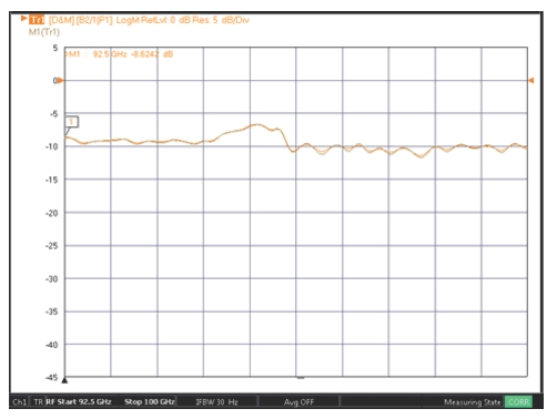
The experiment was then repeated with real-time power correction ON (see Figure: Drive Power Changed After Calibration – Real-time Power Correction On). This time power levels of -10 dBm (brown) and -30 dBm (orange) were used to better illustrate the benefits of direct measurement of drive power. The deviation in this case was < 0.2 dB. Note that the curves would only be expected to overlay if the DUT linearity was absolutely perfect. In this range, this particular DUT was expected to be relatively linear so only minor deviations were anticipated.
Drive Power Changed After Calibration – Real-time Power Correction On