Pulsed measurements are also quite relevant at millimeter-wave frequencies, particularly when striving for isothermal operation of on-wafer devices. The purpose of this section is to explore how the setups and measurements change when going to the broadband/millimeter-wave realm with ME7838 broadband systems (with maximum frequencies currently ranging from 110 GHz to 226 GHz).
Basics
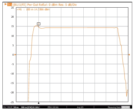
Since the pulse measurement options are based on wideband IF processing, one would expect that, on the surface, little would change when going to millimeter-wave frequencies. Indeed, this is largely the case. Pulse timing control and synchronization remain the same as for the base VNA, but one may notice added jitter for the finer timing resolutions because the available IF bandwidth in the modules for the broadband systems is slightly reduced. Still, high resolution measurements are possible; an 81 GHz example profile measurement is shown in Figure: Example Millimeter-wave Profiling Measurement Illustrates Available Resolution with a time range of 250ns, and considerable detail is evident.
Example Millimeter-wave Profiling Measurement Illustrates Available Resolution
If the measurements do not require RF drive modulation, there are not many other differences from pulsed operation with the based VNA. Time-gated power calibrations, which might have been done at DUT output even when the drive was not pulsed, are not available. This is mainly because of the lack of wide instantaneous bandwidth pulsed power sensors at millimeter-wave frequencies (as of this writing).
Millimeter-Wave Measurements with RF Drive Modulation
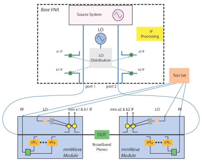
As with lower frequency pulsed measurements with modulated drive, a pulsed test set (or other modulator) is required. The setups do vary slightly because of how the stimulus signal flows to the port. Recall the structure of the broadband system (see Broadband/mmWave Measurements (Option 7, Option 8x) of this guide for more information) as shown in Figure: General Broadband System Architecture for Reference. For frequencies nominally below 54 GHz, the VNA synthesizer directly supplies the drive through (essentially) a pass-through transmission line in the module. Thus, pulse modulation applied in a source loop of the VNA or between port 1 of the VNA and the module will work as would be expected. Accessing through the source loops is preferable if match correction or reversing measurements under 30 GHz are desired (30 GHz is nominally when the module receivers take over; the base VNA receivers are used below that frequency).
General Broadband System Architecture for Reference
Notice that the RF entry into the modules, for the multiplied bands above 54 GHz, presents a bit more of a challenge:
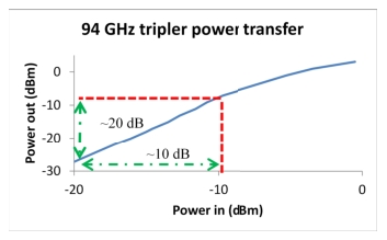
• The modulation has to occur before the module (no later access points are available) so pulsing will be done before the final multiplier. This has both advantages and disadvantages. The Pout-Pin slope of the multipliers is always >1 (an example is shown in Figure: Example Multiplier Transfer Curve) so there is an improvement in on-off isolation. However, the multipliers may introduce some video distortion.
• A source modulator is here placed in the RF drive path and both module port 1 and module port 2 will be modulated when they are driving. The modulator could be placed between the test set and the module as well (slightly less flexible but, since later in the chain, there may be less video distortion; note that the levels in both locations may exceed 5 dBm).
• The RF frequencies going to the modules do not exceed 40 GHz. The minimum frequency on this RF drive path for the module is 26 GHz for 110/125 GHz systems, 18 GHz for 145 GHz systems and 12.75 GHz for 220 GHz systems. The frequency ranges for banded millimeter-wave modules from 3rd-party vendors vary (consult the source multiplier values from the vendor).
• The receive-side modulators in the test set are not particularly useful for millimeter wave as there are no RF loops in the receive path and the frequency range availability would not match anyway. The receive-side modulators could conceivably be used on the IF path (low-band modulators) but there is little de-sense that could cause problems at that level in the architecture.
.
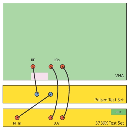
Normal Position for Drive-side Pulsed Modulation for Millimeter-wave Frequencies
• In normal 3739 modes, the system uses IF leveling so the pulsed RF presents some changes in how ALC control works.
• The average signal level at the detection point will be down by 20*log10(duty cycle) so the leveling loop will compensate by increasing the drive level. Thus, if one does nothing, the entry on the power menu will now represent an average power rather than an 'on state' power and the value may have to be dropped considerably to avoid unleveled messages and very high peak powers.
• User power calibrations can be done while pulsed and it will help to manually enter the duty cycle/duty factor on the power meter. With such a calibration, the power menu will again be reading in terms of ‘on state’ power.
• Because of the drop in detected signal level for a given on-state power, the power control range will be reduced from non-pulsed conditions (generally by about the dB form of the duty cycle).
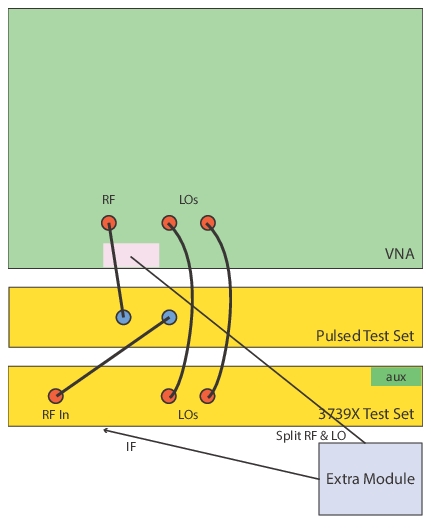
• An auxiliary module can be used to level the system based on CW power (see Figure: Extra Millimeter-wave Module Used as a Leveling Hub) which will simplify the power entry interpretations and calibrations at the expense of additional hardware. This extra module would use a split off sample of the pre-modulator RF drive and a split off sample of the module LO to generate a local IF for leveling. Its control cable would connect to the port 1 position. The main port 1 module's control cable would connect to the aux module connector shown at the right on the test set.
Extra Millimeter-wave Module Used as a Leveling Hub
An extra millimeter-wave module can be used as a leveling hub to simplify power control in pulsed drive scenarios above 54 GHz (IF leveling). This module's job is to sense and level the pre-modulator drive.
• In millimeter-wave multiple source modes, most of the same rules apply. RF leveling is often used here (for frequency converting measurements, for example) but the same issues as discussed above apply since the detection point is in the module (after modulation). A variant, termed VNA-RF leveling, uses a detection point back in the VNA and this can simplify the situation (just as the extra module did for IF leveling). In this case, the power menu and power calibrations would again represent on-state power without duty cycle considerations. Because the detection is before the modulator and the multiplier, the power control will be sensitive at low levels. As with all RF leveling modes, however, power control is limited and will be slightly more so in the pulsed case.
• VNA-RF leveling is not available above 125 GHz so for higher frequency systems, classical remote detection is usually used although the auxiliary module option is available. This gets a bit more complicated in that this situation normally arises in frequency converting measurements so the system LO is not in the right place to create a leveling signal. The DUT output can sometimes be used for leveling or an additional LO can be generated with an external synthesizer.
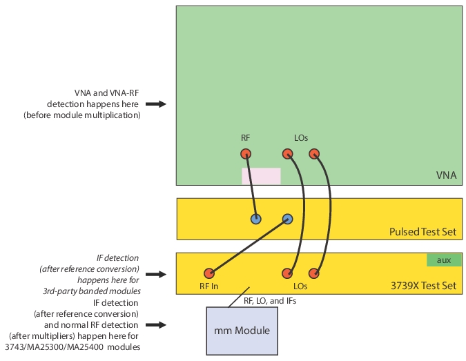
• The detection locations are summarized in Figure: Detection Locations. The methods all have their advantages. IF leveling has the largest control range and best stability but is not available (without added modules as discussed earlier) in frequency converting measurements and there are pulsed power definition complications. RF and VNA leveling are available for frequency converting measurements but have less control range and stability (detection linearity and noise). VNA leveling is more easily defined than RF in a pulsed system and has better detection linearity than RF detection based on the final multiplier, but it is more sensitive since it is early in the chain.
• Software-assisted leveling (see the discussion earlier in this chapter) is available where post-processed reference measurements are used to servo the drive power but are less useful than at microwave frequencies since the transient time constants are different and the starting power accuracies are not as confined.
Detection Locations
I
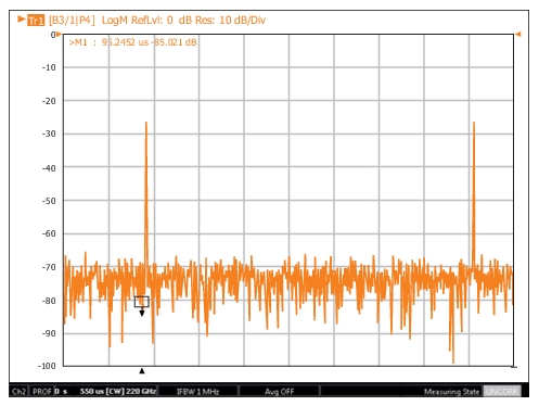
• On four port systems, modulation can be added on paths to both test sets if desired (or to individual modules). The same leveling comments discussed earlier apply here as well. An example ME7838G4 measurement at 220 GHz is shown in Figure: Example 220 GHz Profiling Measurement with RF Drive Modulation where a profile over two periods was being evaluated For this setup, VNA leveling was used, the CW frequency was set for 220 GHz, and the period was set for 400 µs. An internal pulse generator fed the external pulse test set connected in the RF drive path as discussed earlier. The pulse width was set for 5 µs and the delay for 100 µs. The profiling range was set for 550 µs with 551 points and a measurement width of 1µs. This resulted in adjoining measurement windows but this, of course, is not required.
• A receiver calibration only was used for this measurement (on the test 3 receiver) as output power of the DUT was of primary interest. The receiver cal was performed while there was no RF pulsing. Average power was monitored with a power meter (with RF pulsing on and before the DUT was connected) on the on-state power checked manually as the G-band power meter being used did not have a duty cycle entry (as might be seen on lower frequency meters).
Example 220 GHz Profiling Measurement with RF Drive Modulation
The period was relatively long in this example.
• For measurements on banded millimeter-wave setups using 3rd-party millimeter-wave modules, many of the same considerations discussed so far will apply. RF drive modulation would normally be done before the test set.
• The default leveling mode is based on detection in the VNA so the pulse drive would not change things immediately. IF leveling modes are available which would have the same implications as those discussed for the broadband setup.
• There are calibrated VNA-RF leveling modes (detection in the VNA) also as discussed for the broadband systems.
• Anritsu has not validated the pulsed video performance (e.g., are the IFs wide enough, do the multipliers induce video distortion, etc.) on all 3rd-party modules, so we cannot predict behavior in general, but the majority of the modules tried did not show anomalies.
 I
I