• MAIN | Sweep Setup | SWEEP SETUP | Hold Functions | HOLD FUNCTIONS
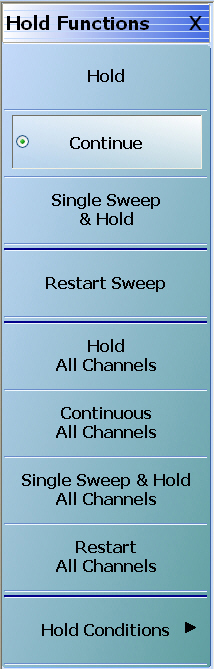
HOLD FUNCTIONS Menu (1 of 2)
HOLD FUNCTIONS Menu – Per-Channel Button Selection Group
The top four (4) buttons of the HOLD FUNCTIONS menu provide hold control for the active trace.
The Hold, Continue, Single Sweep & Hold, and Restart Sweep buttons form a four (4) button selection group where the selection of any one button de-selects the other three (3) buttons on a per channel basis.
Hold
For the active channel, the Hold button pauses the display and stops the channel signal processing. Also, if the Hold All Channels button (described below) is selected, this Hold button is selected.
Continue
For the active channel, the Continue button starts signal processing and resumes the active channel display. Also, if the Continuous All Channels button (described below) is selected, this Continue button is selected.
Single Sweep & Hold
For the active channel, the Single Sweep & Hold button performs a single sweep signal processing, and then holds the display, stops signal processing, and returns the button selection to the Hold button.
Restart Sweep
For the active channel only, the Restart Sweep button restarts signal processing, resumes the active channel display, and then selects the Continue button. To restart sweeps on all channels, use the Restart All Channels button described below.
HOLD FUNCTIONS Menu – Per-System Button Selection Group
The second set of four (4) buttons of the HOLD FUNCTIONS menu provide hold control for instrument on a per-system basis.
The Hold All Channels, Continuous All Channels,Single Sweep & Hold All Channels, and Restart All Channels buttons form a four (4) button selection group where the selection of any one button de-selects the other three (3) buttons on a per-system basis.
Hold All Channels
For all channels, the Hold All Channels button stops signal processing, holds the display, and then selects the Hold button (above).
Continuous All Channels
For all channels, the Continuous All Channels button starts signal processing, resumes the display on all channels, and then selects the Continue button (above).
Single Sweep & Hold All Channels
For all channels, the Single Sweep & Hold All Channels button performs a single sweep signal processing, and then stops signal processing, holds the display, momentarily selects the Single Sweep & Hold button, and then selects the Hold button (above).
Restart All Channels
For all channels, the Restart All Channels button restarts signal processing, resumes the active channel display, and then selects the Continue button. To restart only the active channel, use the Restart Sweep button described above.
Hold Conditions
Select displays the HOLD CONDITIONS menu where toggle settings for Bias Tee, RF, and DUT Protection are available.
The HOLD CONDITIONS menu appearance varies as a 3- or 4-button version depending on the sweep type settings. The prerequisites for each variant is described below with a link to a full description of each menu.
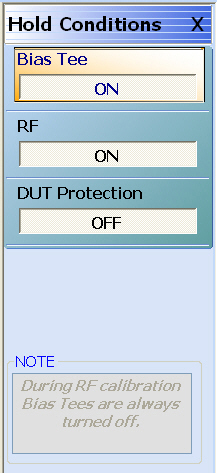
HOLD CONDITIONS Frequency-Based Sweep Menu
If the HOLD CONDITIONS menu has three (3) buttons of Bias Tee, RF, and DUTProtection, Sweep Type is set to one of the following:
• MAIN | Sweep Setup | SWEEP SETUP | Hold Functions | HOLD FUNCTIONS | Hold Conditions | HOLD CONDITIONS Freq-Based Sweep
HOLD CONDITIONS Frequency-Based Sweep Menu
Bias Tee (Off/On)
Select toggles the Bias Tee option off and on during Hold mode. Note that during RF calibration, Bias Tees are turned off.
RF (Off/On)
Select toggles the Radio Frequency (RF) option off and on during Hold mode.
DUT Protection (Off/On)
Toggles the Device Under Test (DUT) protection off and on. The DUT Protection mode puts the instrument on hold with bias and RF turned off after powering up the instrument. This protects a device that is connected to the VNA. Note that DUT protection only applies after the software is fully loaded and operational. During the boot-up process, every effort has been taken to protect devices, but for full protection, sensitive devices should not be connected to the VNA during power-up.
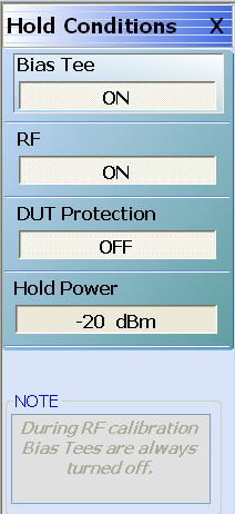
HOLD CONDITIONS Power-Based Sweep Menu
Menu Identification and Variants
• The appearance and button availability of the HOLD CONDITIONS menu depends on settings on the SWEEP TYPE menu.
• Consult the section above for menu identification and prerequisites.
• MAIN | Sweep Setup | SWEEP SETUP | Hold Functions | HOLD FUNCTIONS | Hold Conditions | HOLD CONDITIONS Power-Based Sweep
HOLD CONDITIONS Power-Based Sweep Menu
Bias Tee (Off/On)
Select toggles the Bias Tee option off and on during Hold mode. Note that during RF calibration, Bias Tees are turned off.
RF (Off/On)
Select toggles the Radio Frequency (RF) option off and on during Hold mode.
DUT Protection (Off/On)
Toggles the Device Under Test (DUT) protection off and on. The DUT Protection mode puts the instrument on hold with bias and RF turned off after powering up the instrument. This protects a device that is connected to the VNA. Note that DUT protection only applies after the software is fully loaded and operational. During the boot-up process, every effort has been taken to protect devices, but for full protection, sensitive devices should not be connected to the VNA during power-up.
Hold Power
On a per-system basis, sets the hold power level. Select displays the Hold Power field toolbar.
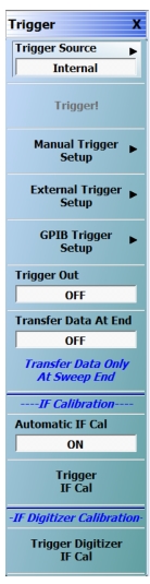
The availability of the Trigger! button depends on the setting of Trigger Source. If Trigger Source is set to Internal, External, or GPIB, the button is unavailable.
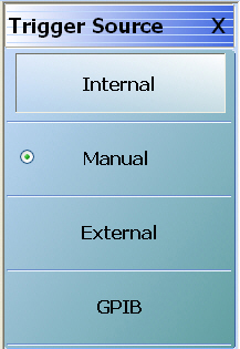
Trigger Source
Select displays the Trigger Source menu which allows trigger source choices of Internal, Manual, External, or GPIB. The configuration and settings for each trigger source type are defined by the buttons below.
The Trigger button manually triggers the measurement. Trigger Source (above) must be set to manual.
Manual Trigger Setup
Select displays the MANUAL TRIGGER menu and sets what measurement will be made when the trigger is manually selected. Measurement options can be based per-point, per-sweep (or per-port), per-channel, or for all channels.
External trigger mode allows a rear panel input to start a measurement based per-point, per-sweep (or per-port), per-channel, or for all channels with configuration options between the external triggering device and the instrument. Select displays the EXT TRIGGER menu.
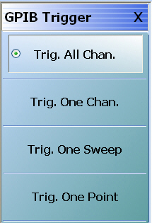
The GPIB trigger mode allows a GPIB trigger command to start a measurement based per-point, per-sweep (or per-port), per-channel, or for all channels. Select displays the GPIB TRIGGER menu.
Note:Trigger Out functionality is enabled or disabled under the conditions and application usage indicated in Table: Trigger Out Blocking.
This toggle allows the user to have Trigger Out functionality for internal and manual trigger modes (in external triggering, the handshake control enables this trigger out feature). For example, if the user toggles Trigger Out to On while in internal triggering mode, the VectorStar will control measurement timing with its internal trigger and the trigger out BNC connector will become active. A positive going pulse will appear at this connector at the time of the measurement (with some finite latency) at each point.
Transfer Data At End (Off/On)
Select toggles feature On/Off. When toggled ON, the transfer of data is prohibited until end of sweep to minimize point to point triggering time. This feature is useful for optimizing speed in a rapid triggering environment.
Automatic IF Cal (Off/On)
Select toggles the Automatic Intermediate Frequency Calibration (Automatic IF Cal) calibration mode off and on.
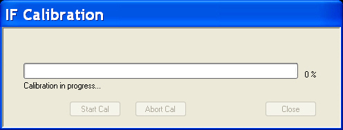
Trigger IF Cal
The Trigger IF Cal button starts the IF calibration and displays the IF CALIBRATION dialog box with a completion progress bar.
TRIGGER SOURCE Menu Auto-Return Button Selection Group
In the TRIGGER SOURCE menu, the Automatic Internal, Manual Internal, External, and GPIB buttons are members of a four (4) button selection group. Selection of any one button de-selects the other three buttons and automatically returns to the TRIGGER menu.
Internal (Trigger Source)
Select sets triggering to be automatically created within the instrument. Internal triggering mode is an automatically triggered point-by-point measurement that is controlled by the instrument internal software.
Manual (Trigger Source)
Select sets triggering to be manually triggered by the user. The default setting is on a per-channel basis. The maximum setting is for all channels.
External (Trigger Source)
Select sets triggering to be created externally by another instrument and sensed through an external port/connector.
GPIB (Trigger Source)
Select sets triggering to be through an external General Purpose Interface Bus (GPIB) device and communicated to the instrument via a GPIB network.
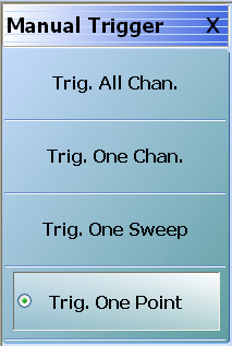
MANUAL TRIGGER Menu
Manual trigger mode is triggered by the user from the TRIGGER menu to start a measurement based per-point, per-sweep (or port), per-channel, or for all channels.
In the MANUAL TRIGGER menu, the Trig. All Chan., Trig. One Chan., Trig. One Port, and Trig. One Point buttons are members of a four (4) button selection group. Selection of any one button de-selects the other three buttons. After making a selection, click Back to return to the TRIGGER menu.
Trig. All Chan. (Manual Trigger)
The Trigger All Channels button sets the trigger to measure values for all channels.
Trig. One Chan. (Manual Trigger)
The Trigger One Channel button sets the trigger to measure value for the active channel only.
Trig. One Sweep (Manual Trigger)
The Trigger One Sweep button sets the trigger to measure values for one sweep only.
Trig. One Point (Manual Trigger)
The Trigger One Point button sets the trigger to measure values for one point only.
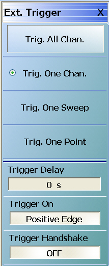
EXT. TRIGGER Menu
External trigger mode allows a rear panel input to start a measurement based per-point, per-sweep (or per-port), per-channel, or for all channels. The EXT. TRIGGER menu configuration options allow for selection of either a positive or negative signal edge, a trigger delay, and signal handshaking between the external triggering device and the instrument.
In the Ext. Trigger menu, the Trig. All Chan., Trig. One Chan., Trig. One Port, and Trig. One Point buttons are members of a four (4) button selection group where selection of any one button de-selects the other three.
Trig. All Chan. (External Trigger)
The Trigger All Channels button sets the external trigger to measure values for all channels.
Trig. One Chan. (External Trigger)
The Trigger One Channel button sets the external trigger to measure values for one channel only.
Trig. One Sweep (External Trigger)
The Trigger One Sweep button sets the external trigger to measure values for one sweep only.
Trig. One Point (External Trigger)
The Trigger One Point sets the external trigger to measure values for one point only.
Trigger Delay (Time) (External Trigger)
Trigger delay sets the time interval between when the instrument received the trigger signal and when the triggered measurement starts.
Select displays the Trigger Delay field toolbar and allows the user to enter a trigger delay time in units of seconds (s), milliseconds (ms), microseconds (us), or nanoseconds (ns).
Trigger On (Positive Edge/Negative Edge) (External Trigger)
Select toggles the triggering point to be on either the positive edge or negative edge of the triggering signal. The default value is positive edge.
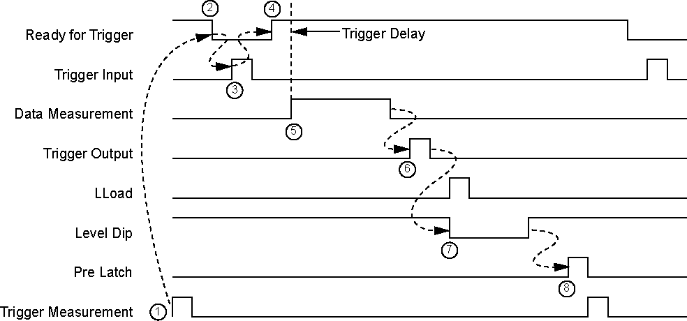
Trigger Handshake (Off/On) (External Trigger)
If triggering handshaking is on, the instrument provides a Ready for Trigger and an Output Trigger signal from the rear panel.
• The instrument sends a Ready for Trigger signal to specify if the instrument is ready or not to receive a triggering signal.
• The instrument sends an Output Trigger signal when the triggered measurement is complete.
Select toggles whether the trigger handshake is off or on. The default value is OFF.
• MAIN | Sweep Setup | SWEEP SETUP | Sweep Time Setup | SWP TIME SETUP
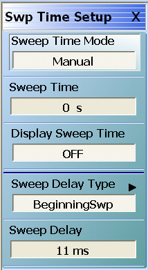
SWP TIME SETUP (SWEEP TIME SETUP) Menu
Sweep Time Mode (Auto/Manual)
If toggled to Manual, the Sweep Time button is available. If toggled to Auto, the button is unavailable.
Sweep Time
The Sweep Time Mode must be set to Manual for the Sweep Time button to be available. Select displays the Sweep Time field toolbar. Note that the sweep delay time set here is also set on the SWEEP DELAY menu.
Display Sweep Time (On/Off)
Select toggles the display of the sweep time ON and OFF.
Sweep Delay Type
Select displays the SWEEP DELAY menu where the delay can be set as OFF, or as begin sweep, phase locked, or load pulse. In addition, the sweep delay time value can be set.
• MAIN | Sweep Setup | SWEEP SETUP | Sweep Time Setup | SWP TIME SETUP | Sweep Delay Type | SWEEP DELAY
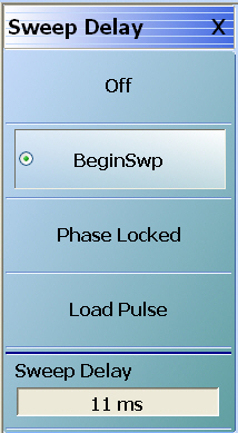
SWEEP DELAY Menu
Auto-Return Button Group
The top four (4) buttons on the SWEEP DELAY menu form an auto-return button selection group. Selecting the either the Off, Begin Swp, Phase Locked, or Load Pulse button de-selects the other three (3) buttons and auto-returns to the SWPTIME SETUP menu.
The fifth button, Sweep Delay, displays the Sweep Delay field toolbar allowing input of sweep delays in units of seconds (s), milliseconds (ms), microseconds (us), and nanoseconds (ns).
Off
Select turns the sweep delay off and auto-returns to the SWP TIME SETUP menu. The sweep delay status of OFF is displayed in the Sweep Delay Type button.
Begin Swp
Select sets the sweep delay to Beginning Sweep and auto-returns to the SWP TIME SETUP menu. At the beginning of each sweep, the first point is phase locked, and then the user-defined delay time period occurs. After the delay time, the sweep is completed. On the SWP TIME SETUP menu, the Sweep Delay Type is shown as BeginningSwp.
Phase Locked
Select sets the sweep delay to Phase Locked and auto-returns to the SWP TIME SETUP menu. The sweep starts, the hardware phase locks at each frequency, and the user-defined delay time period occurs. The sweep continues until the sweep is completed. On the SWP TIME SETUP menu, the Sweep Delay Type is shown as PhaseLocked.
Load Pulse
Select sets the sweep to Load Pulse and auto-returns to the SWP TIME SETUP menu. The sweep starts, and while sweeping, the VNA digital signal processor sends a command to load the programming for the next frequency. At this point, the user-defined delay time period occurs. The sweep-load-delay cycle repeats for every point in the sweep.
Sweep Delay
Select displays the Sweep Delay field toolbar where the time delay can be set as s, ms, us, or ns. Note that the sweep delay time set here can also be set on the SWEEP DELAY menu.
After setting the sweep delay time, select the Back button to return to the SWP TIME SETUP menu.