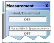
When the IMDView application is active, the following MEASUREMENT menu buttons are disabled: Embed/De-embed, Imped. Transf., Optical Measurements, Perform Optical Measurements, Post-Processing Order, Edit Embed/De-embed, Line Type, and Dielectric.
When the pointer is placed over a menu item, a tool tip noting “Not available in IMDView” will appear.
Measurement Menu Note (when Spectrum Analysis is active)
When the Spectrum Analysis application is active, the following MEASUREMENT menu buttons are disabled: Embed/De-embed, Imped. Transf., Optical Measurements, Perform Optical Measurements, Post-Processing Order, Edit Embed/De-embed, and Line Type.
When the pointer is placed over a menu item, a tool tip noting “Not available in Spectrum Analysis” will appear.
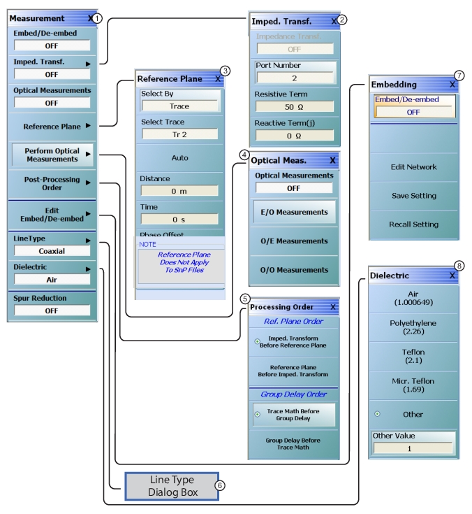
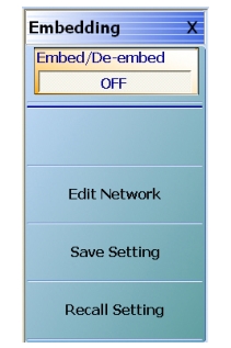
Embed/De-embed (Off/On)
Select toggles the embedding/de-embedding function off and on.
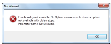
If a successful calibration has not been previously performed, select displays a warning message. Click OK to clear.
Imped Transf (Impedance Transformation)
Select impedance transfer displays the IMPED TRANSF menu.
Select displays the DIELECTRIC menu and allows the user to select from pre-defined dielectric materials or create the value for a user-defined material.
Select toggles Spur Reduction off and on. Turning Spur Reduction ON eliminates the effect of spurious signals being reflected back from DUTs such as deep stop-band filters, which will cause a decrease in dynamic range. Spur Reduction ON turns off the unused test receiver during each S-parameter measurement, thus requiring 4 sweeps to measure all 4 S-parameters.
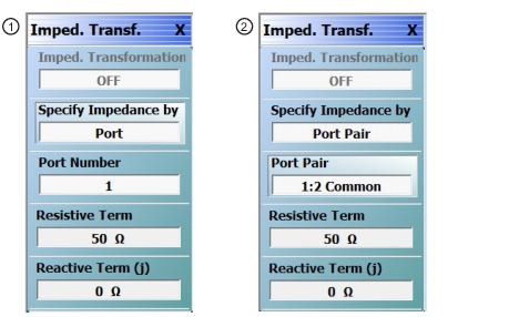
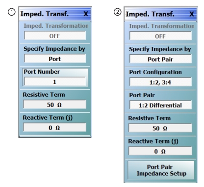
IMPED. TRANSF. (IMPEDANCE TRANSFORMATION) Menu – 4-Port VNAs
1. IMPEDANCE TRANSFORMATION Menu – Specify Impedance by Port
2. IMPEDANCE TRANSFORMATION Menu – Specify Impedance by Port Pair
Impedance Trans (Off/On)
Select toggles impedance transformation off and on. Calibration is required to enable impedance transformation.
Specify Impedance by
Toggles between Port and Port Pair.
Port Number
When Specify Impedance by is set to Port, select displays the SELECT PORT dialog box with large easy-to-select buttons. Selecting a port auto-returns to the IMPED. TRANSF. menu.
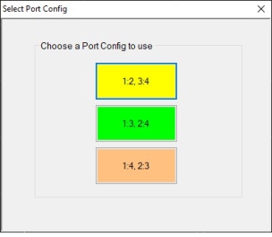
Port Configuration
Select displays the SELECT PORT CONFIG dialog box with large, easy-to-select buttons. Selecting a port configuration auto-returns to the IMPED. TRANSF. menu.
SELECT PORT CONFIG Dialog Box
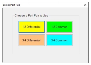
Port Pair
Select displays a SELECT PORT PAIR dialog box with large, easy-to-select buttons. Selecting a port pair auto-returns to the IMPED. TRANSF. menu.
When the port configuration is changed, the port pair shown on the menu will be the default one for that particular Port Configuration. For Port Configuration 1:2,3:4 the default port pair is 1:2 Differential, for 1:3,2:4 the default port pair is 1:3 Differential, and for 1:4,2:3 the default port pair is 1:4 Differential.
Example: SELECT PORT PAIR Dialog Box for Port Configuration 1:2, 3:4
Resistive Term (Ohms)
Select displays the Resistive Term field toolbar and allows the user to define the resistive term for the port pair shown in the menu in Ohms. The default value is 50.000 ohms.
Resistive Term Field Toolbar
Reactive Term (j) (Ohms)
Select displays the Reactive Term field toolbar and allows the user to define the reactive (j) term for the port pair shown in the menu in Ohms.
Reactive Term Field Toolbar
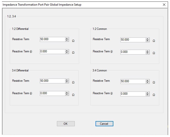
Port Pair Impedance Setup
Select displays the IMPEDANCE TRANSFORMATION PORT PAIR GLOBAL IMPEDANCE SETUP dialog box, which allows the user to set all the reactive and resistive terms for all the port pairs for a given port configuration at once.
Example: IMPEDANCE TRANSFORMATION PORT PAIR GLOBAL IMPEDANCE SETUP Dialog Box for Port Configuration 1:2,3:4
REFERENCE PLANE Menu
A simplified means of performing de-embedding (and embedding in some contexts) can be accomplished using reference plane control. The function of this control is to remove transmission line lengths from the data. By entering a time or distance, this length of line will be removed (negative lengths are allowed to effectively add length). Various dielectrics and the full dispersion choices are available.
The VectorStar VNA supports both per-port and per-trace reference plane extensions, whereas other instruments support only either per-port or per-trace. As a result, if the programming language mode is changed from Native the reference plane control selections may be affected. (e.g., Lightning only supports per-trace reference planes and the HP8510 only supports per-port reference planes).
Button Functionalities when IMDView (Option 44) is Enabled
When IMDView application is ON, the following Reference Plane menu buttons are disabled:
• Select By, Select Port, Auto (Length), Auto (Loss & Length), Distance, Time, Phase Offset, and the Freq. Dependent loss fields (Reference Loss and Reference Frequency)
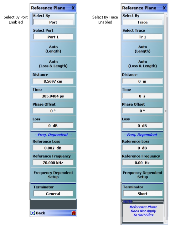
Select By (Port/Trace)
The Select By toggle button changes between Select Reference Plane By Port and Select Reference Plane By Trace. When the selection is changed, the name of the next button changes as:
• Select By = Port: The button below is set to Select Port. If Port is selected, reference plane adjustments are on a per-port basis.
• Select By = Trace: The button below is set to Select Trace. If Trace is selected, reference plane adjustments are on a per-trace basis.
Select Port (Port 1/Port 2)
This button is only present when the Select By button above is set to Port. If present, when the VNA is in 2-Port Mode, select toggles between Port 1 or Port 2. If present, when the VNA is in 4-Port Mode, select displays the SELECT PORT (REFERENCE PLANE) dialog box with large easy-to-select buttons. Selecting a port auto-returns to the REFERENCE PLANE menu.
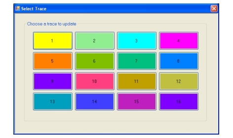
Select Trace
This button is only present when the Select By button above is set to Trace. If present, the reference plane adjustments available in the buttons and toolbars following can be modified on a per-trace basis. Selecting the button displays the large SELECT TRACE Dialog Box (below) where the trace number can be selected. After a trace is selected, the focus auto-returns to the REFERENCE PLANE menu.
Auto (Length)
The Auto (Length) button automatically extends the test port location by removing the effects of the electrical delay of a device.
Auto (Loss & Length)
When the Auto (Loss & Length) is used, fits are done on both the phase and the magnitude independently. Values for the fit parameters are entered in the appropriate menu fields and the adjustments applied to the trace data.
Distance (Reference Plane)
Select displays the Distance field toolbar. Allows the user to enter a distance in units of km (kilometers), m (meters), cm (centimeters), mm (millimeters), or µm (micrometers).
Time (Reference Plane)
Select displays the Time field toolbar. Allows the user to enter a reference time in units of s (seconds), ms (milliseconds), us (microseconds), ns (nanoseconds), or ps (picoseconds).
Phase Offset (Degrees) (Reference Plane)
Select displays the Phase Offset field toolbar. Allows the user to enter a phase offset in degrees from –360º (degrees) to +360º in 0.01º increments.
Loss (dB) (Reference Plane)
Displays the Loss (dB) field toolbar. Allows the user to enter a loss factor in dB.
Freq. Dependent Fields
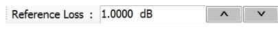
Reference Loss
Displays current Reference Loss setting in dB. Selecting this field opens the Reference Loss field toolbar.
Reference Frequency
Displays current Reference Loss setting in dB. Selecting this field opens the Reference Frequency field toolbar.
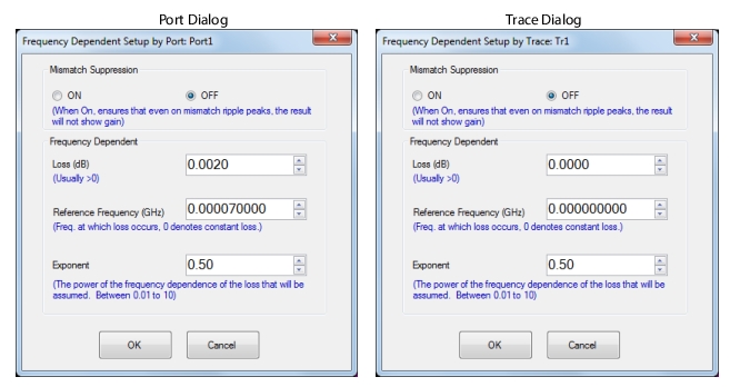
Frequency Dependent Setup
Opens the FREQUENCY DEPENDENT SETUP (by Port or by Trace) dialog box. This frequency-dependent loss aspect of reference plane extension can be useful for very simplified de-embedding of fixtures or cabling.
Depending on whether Select By Port or Select By Trace is selected on the REFERENCE PLANE menu, upon clicking Frequency Dependent Setup button, the appropriate FREQUENCY DEPENDENT SETUP (by Port or by Trace) dialogappears.
• MAIN | Measurement | MEASUREMENT | Reference Plane | REFERENCE PLANE | Frequency Dependent Setup | FREQUENCY DEPENDENT SETUP
FREQUENCY DEPENDENT SETUP Dialog
Mismatch Suppression
When Mismatch Suppression is activated, the fitting process is modified so any ripple peaks will stay below the nominal initial value of the parameter in question. The concept is to limit that amount of loss correction so that no ripple peaks in the adjusted result exceed the initial (lowest loss) value of the parameter. If the DUT has very low loss at low frequency, not suppressing the effect of mismatch-induced ripple could result in an adjusted parameter value above 0 dB which may be objectionable in some applications.
Frequency Dependent Settings:
Loss
Usually greater than zero (but can be negative for gain). This is the loss at some known frequency and then a loss at other frequencies will be calculated using the frequency raised to the 'exponent' power.
Reference Frequency
Frequency at which the loss specified above is defined. The loss at other frequencies is scaled by (frequency/(reference frequency))^n where n is the exponent specified next.
Exponent
Exponent has a default value of 0.5 which tends to describe loss in coaxial lines and in coplanar waveguide rather well for many materials. The exponent may be closer to 1 for microstrip structures and other values for other geometries. The allowed range for the exponent is 0.01 to 10 but it is fairly rare to get outside the range of 0.25 to 2.
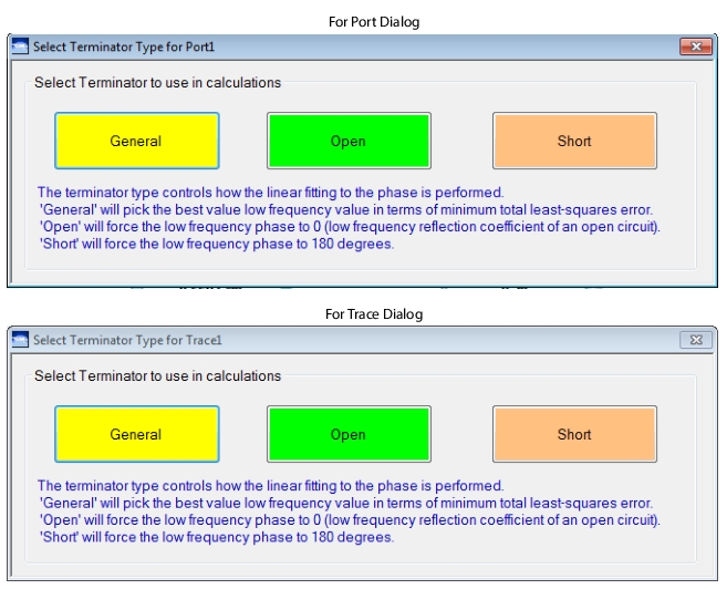
SELECT TERMINATOR TYPE Dialog Box
Depending on whether Select By Port or Select By Trace is selected on the REFERENCE PLANE menu, upon clicking Terminator button, the appropriate SELECT TERMINATOR TYPE (for Port or for Trace) dialogappears.
• MAIN | Measurement | MEASUREMENT | Reference Plane | REFERENCE PLANE | Terminator | SELECT TERMINATOR TYPE
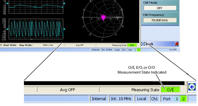
Depending on the EO_OE_OO status in the CHX file, and once the E/O or O/E or O/O measurement setup through the respective dialog is complete, the Channel Status on the display will indicate an O/E, E/O, or O/O measuring state as shown in Figure: O/E – E/O – O/O Measuring State Indication.
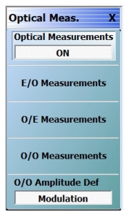
O/O Amplitude Def
• Toggle button selects between Modulation and Optical Power. Only available for O/O Measurements. This allows a choice in the domain of reference (in terms of sideband amplitude in the modulation sense or inferred differences in net optical power). There is a 2x difference in dB terms.
O/E – E/O – O/O Measuring State Indication
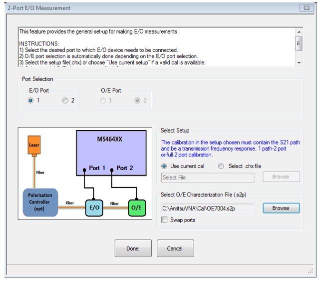
2-Port E/O Measurement Dialog Box
Upon clicking E/O Measurements button, the 2-PORT E/O MEASUREMENT dialog appears.
The E/O MEASUREMENT dialog enables the user to determine the microwave frequency response characteristics of E/O devices (such as E/O modulators).
2-PORT E/O MEASUREMENT Dialog
Port Selection Radio Buttons
• Select the desired port to which E/O device needs to be connected. The O/E port selection is automatically done depending on the E/O port selection.
Select Setup
• Use current calibration setup or browse to CHX file and select. The option to use the current calibration will be enabled only if a valid calibration exists.
Select O/E Characterization File (.s2p)
• Browse to and select .s2P file.
Swap Ports
• Check the Swap Ports option if the S-parameters assignment present in the file needs to be swapped.
On clicking Done button, the calibration in the selected CHX file is loaded, if necessary, and the calibration error terms are modified using the .s2p file data.
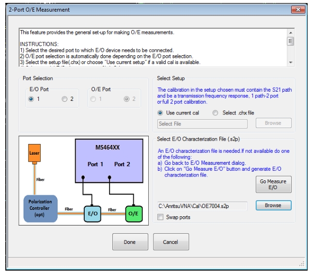
2-Port O/E Measurement Dialog Box
Upon clicking the O/E Measurements button, the 2-PORT O/E MEASUREMENT dialog appears.
The O/E MEASUREMENT dialog enables the user to determine the microwave frequency response characteristics of O/E devices (such as O/E detectors and receivers).
2-PORT O/E MEASUREMENT Dialog
Port Selection Radio Buttons
• Select the desired port to which E/O device needs to be connected. The O/E port selection is automatically done depending on the E/O port selection.
Select Setup
• Use current calibration setup or browse to CHX file and select. The option to use the current calibration will be enabled only if a valid calibration exists.
Select E/O Characterization File (.s2p)
• Browse to and select a valid s2p file. If an E/O file is not available, do one of the following:
• Go back to the Optical Meas. menu, select E/O MEASUREMENT dialog and after performing an E/O measurement, save the data in .sNp format.
-OR-
• Use the Go Measure E/O button to generate a .sNp file:
Go Measure E/O Button
• Click the Go Measure E/O button (after selecting a valid port configuration and CHX file), which opens the MEASURE E/O dialog shown in Figure: MEASURE E/O Dialog. In this dialog, using the reference O/E file selected, the E/O data will be saved in a .s2p file format. Now this saved E/O file is available for the O/E measurement in the parent dialog (Figure: 2-PORT O/E MEASUREMENT Dialog).
Swap Ports
• Check the Swap Ports option if the S-parameters assignment present in the file needs to be swapped.
Done/Cancel
• On clicking the Done button, the calibration in the selected CHX file is loaded and the calibration error terms are modified using the .s2p file data.
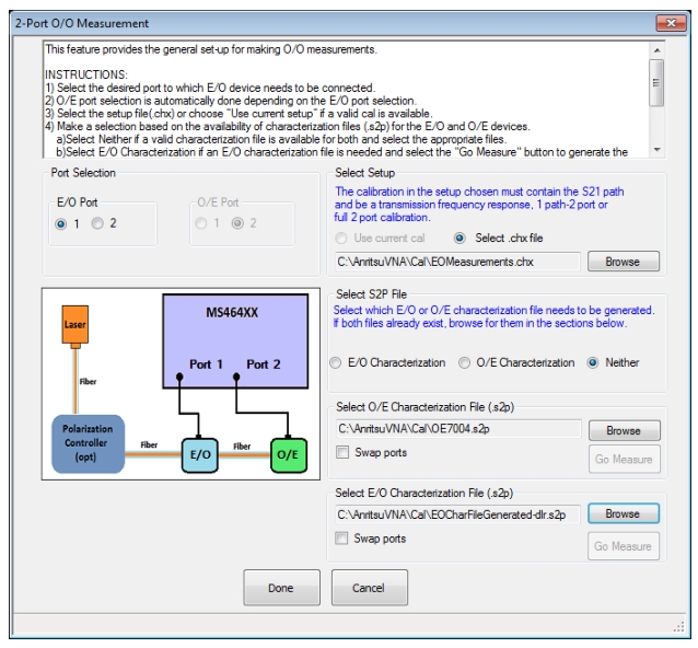
2-Port O/O Measurement Dialog Box
Upon clicking the O/O Measurements button, the 2-PORT O/O MEASUREMENT dialog appears.
The O/O MEASUREMENT dialog enables the user to determine the microwave frequency response characteristics of certain purely optical (O/O) components (couplers, amplifiers, filters, etc.). Although a fiber is shown as the only element between the detector and modulator in Figure: 2-PORT O/O MEASUREMENT Dialog, an optical DUT may be there for O/O measurements.
The O/O measurement is somewhat like the E/O and O/E measurement setups in series; both the detector and the modulator must be de-embedded to leave the reference planes in the optical domain. As suggested by Figure: 2-PORT O/O MEASUREMENT Dialog, if both .s2p files exist, their file names can be entered directly and the de-embedding will ensue.
2-PORT O/O MEASUREMENT Dialog
When measuring O/O devices, the characteristics of both O/E and E/O devices must be known. If a file for one does not already exist, the GO MEASURE E/O dialog shown in Figure: MEASURE E/O Dialog can help in doing the intermediate measurement with the help of the file for the other device (usually a calibration O/E device such as the MN4765X). At least one converter must have a .s2p file to do the measurement. This Go Measure process allows one to enter the known device’s file and to define the file name for the newly created file.
Note that the .s2p file name for the known device is assumed to be the same as that used on the main O/O dialog as this device normally doesn’t change between Measure and O/O configuration steps. If a different device is to be used, the file name on the main O/O dialog can simply be changed after the Measure process is completed.
Port Selection Radio Buttons
• Select the desired port to which E/O device needs to be connected. The O/E port selection is automatically done depending on the E/O port selection.
Select Setup
• Use current calibration setup or browse to CHX file and select. The option to use the current calibration will be enabled only if a valid calibration exists.
Select S2P File
Make a selection based on the availability of characterization files (.s2p) for the E/O and O/E devices.
• Select Neither if a valid characterization file is available for both, then select the appropriate files.
• Select E/O Characterization if an E/O characterization file is needed and select the Go Measure button.
• Select O/E Characterization if an O/E characterization file is needed and select the Go Measure button.
Go Measure Buttons
• If the .s2p file does not exist, clicking this button opens the MEASURE E/O (or MEASURE O/E) dialog shown in Figure: MEASURE E/O Dialog.
Here, one can navigate and select the O/E file, then create a name for the E/O .s2p file to be created when Measure Device is clicked.
Swap Ports
• Check the Swap Ports option if the S-parameters assignment present in the file needs to be swapped.
Done/Cancel
On clicking the Done button (shown in Figure: 2-PORT O/O MEASUREMENT Dialog), the calibration in the selected CHX file is loaded and the calibration error terms are modified using the .s2p file data.
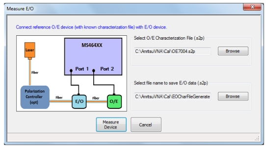
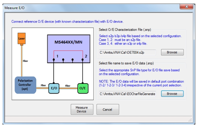
2-Port MEASURE E/O Dialog Box
On either the O/E Measurement or O/O MEASUREMENT dialog, clicking on the Go Measure button displays the MEASURE E/O dialog shown in Figure: MEASURE E/O Dialog.
The calibration in the selected CHX file is loaded and the S-parameters measured with the loaded calibration will be modified by the reference O/E characterization data when Measure Device is clicked. This modified S-parameter data is saved as a .s2p file in the location designated for E/O data.
MEASURE E/O Dialog
Connect Reference O/E Device (that has a known characterization file) With E/O Device
• After connection, select O/E file and enter or select E/O file:
Select O/E Characterization File (.s2p)
• Browse to and select the reference O/E characterization file (.s2p).
Select File Name to Save E/O Data (.s2p)
• Browse to the desired location, then enter or select an existing (.s2p) file name for the E/O characterization file that will be generated.
Click on Measure Device
• After saving the E/O data, the user is returned to the parent O/E MEASUREMENT or O/O MEASUREMENT dialog to complete the measurement.
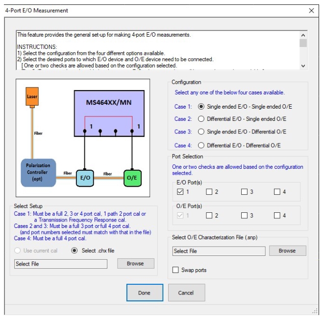
4-PORT E/O MEASUREMENT Dialog Box
Upon clicking E/O Measurements button, the 4-PORT E/O MEASUREMENT dialog appears.
The E/O MEASUREMENT dialog enables the user to determine the microwave frequency response characteristics of E/O devices (such as E/O modulators).
4-PORT E/O MEASUREMENT Dialog
Configuration
• Select the configuration from the four different options available.
Port Selection
Select the desired ports to which E/O device and O/E device need to be connected. (One or two checks are allowed based on the configuration selected. The O/E ports are also selectable but the current E/O selection numbers will be grayed out and unavailable.
Select Setup
• Use current calibration setup or browse to CHX file and select. The option to use the current calibration will be enabled only if a valid calibration exists.
Select O/E Characterization File (.sNp)
• Select a valid O/E characterization file (.s2p if the O/E device is single-ended, .s3p/.s4p if the O/E device is differential).
• For case 4, a dominant path (in the case of asymmetric DUTs) is considered to run from the lower numbered E/O port to the O/E port (and another dominant path between the remaining ports).
• Reconnect the DUT if necessary.
Swap Ports
• In the case of a .s2p file, use the Swap Ports checkbox option if the S-parameters assignment present in the file need to be swapped.
• In the case of a .s3p file: 1:2 and 2:3 paths are dominant (S21>S12 and S23>S32)
• In the case of a .s4p file: 1:2 and 3:4 paths are dominant (S21>S12 and S43>S34)
Reassign Ports
• Use the port reassignment dialog by clicking on the Reassign Ports button if the dominant paths are different from the above.
Done/Cancel
• Upon clicking the Done button, the calibration in the selected CHX file is loaded and the calibration error terms are modified using the O/E characterization file data.
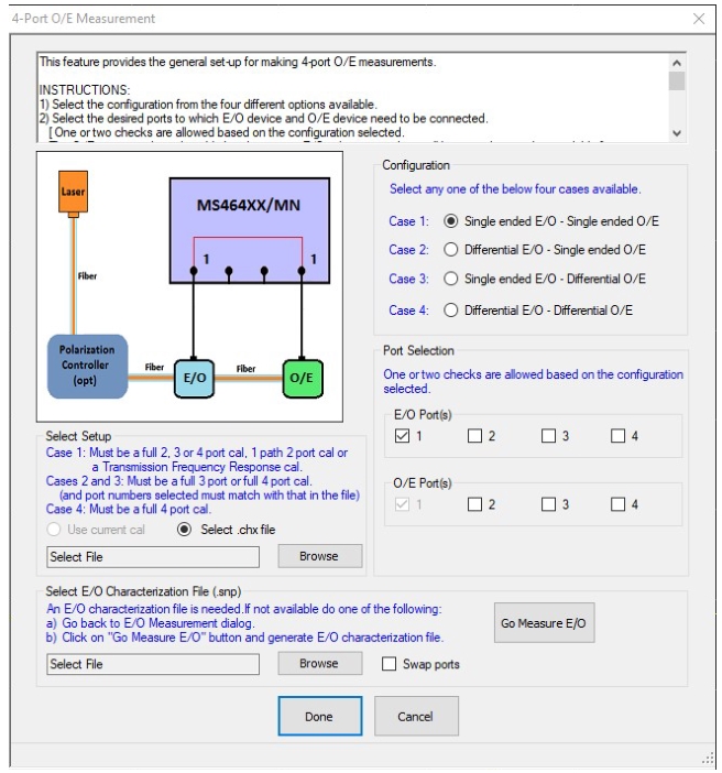
4-PORT O/E MEASUREMENT Dialog Box
Upon clicking O/E Measurements button, the 4-PORT O/E MEASUREMENT dialog appears.
The O/E MEASUREMENT dialog enables the user to determine the microwave frequency response characteristics of O/E devices (such as O/E detectors and receivers).
4-PORT O/E MEASUREMENT Dialog
Configuration
• Select the configuration from the four different options available.
Port Selection
• Select the desired ports to which E/O device and O/E device need to be connected. One or two checks are allowed based on the configuration selected. The O/E ports are also selectable but the current E/O selection numbers will be greyed out and unavailable.
Select Setup
• Use current calibration setup or browse to CHX file and select. The option to use the current calibration will be enabled only if a valid calibration exists.
Select E/O Characterization File (.sNp)
• Select a valid E/O characterization file (.s2p if the E/O device is single-ended, .s3p/.s4p if the E/O device is differential).
• For Case 4 Configuration, a dominant path (in the case of asymmetric DUTs) is considered to run from the lower numbered E/O port to the O/E port (and another dominant path between the remaining ports).
• Reconnect the DUT if necessary.
Go Measure E/O Button
• If an E/O file is not available do one of the following:
• Go back to E/O Measurement dialog and after performing E/O measurement, save the data in .sNp format.
-OR-
• Use the "Go Measure E/O" button to generate a .sNp file:
Click the Go Measure E/O button (after selecting a valid port configuration and CHX file), which opens the Measure E/O dialog shown in Figure: MEASURE E/O Dialog – 4-Port. In this dialog, using the reference O/E file selected, the E/O data will be saved in a file format (.s2p/.s3p/.s4p – depending on the configuration selected). Now this saved E/O file is available for the O/E measurement in the parent dialog (Figure: 4-PORT O/E MEASUREMENT Dialog).
Swap Ports
• In the case of a .s2p file, use the Swap Ports checkbox option if the S-parameters assignment present in the file need to be swapped.
• In the case of a .s3p file: 1:2 and 2:3 paths are dominant (S21>S12 and S23>S32)
• In the case of a .s4p file: 1:2 and 3:4 paths are dominant (S21>S12 and S43>S34)
Reassign Ports
• Use the port reassignment dialog by clicking on the Reassign Ports button if the dominant paths are different from the above.
Done/Cancel
• Click "Done" to perform O/E measurement.
On clicking the Done button, the calibration in the selected CHX file is loaded and the calibration error terms are modified using the O/E characterization file data.
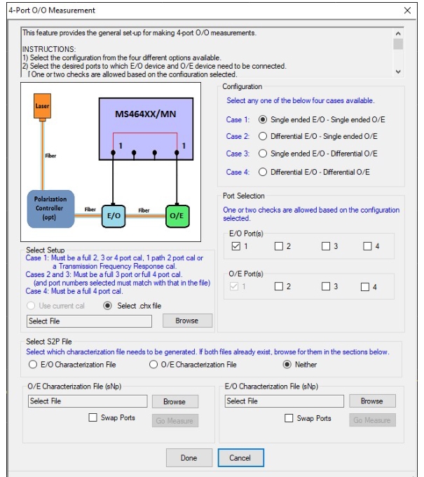
4-PORT O/O MEASUREMENT Dialog Box
Upon clicking O/O Measurements button, the 4-PORT O/O MEASUREMENT dialog appears.
The O/O MEASUREMENT dialog enables the user to determine the microwave frequency response characteristics of certain purely optical (O/O) components (couplers, amplifiers, filters, etc.). Although a fiber is shown as the only element between the detector and modulator in Figure: 4-PORT O/O MEASUREMENT Dialog, some optical DUT may be there for O/O measurements.
The O/O measurement is somewhat like the E/O and O/E measurement setups in series; both the detector and the modulator must be de-embedded to leave the reference planes in the optical domain. As suggested by dialog, if both .sNp files exist, their file names can be entered directly and the de-embedding will proceed.
4-PORT O/O MEASUREMENT Dialog
When measuring O/O devices, the characteristics of both O/E and E/O devices must be known. If a file for one does not already exist, the MEASURE E/O dialog (or MEASURE O/E dialog) shown in Figure: MEASURE E/O Dialog – 4-Port can help in doing the intermediate measurement with the help of the file for the other device (usually a calibration O/E device such as the MN4765X). At least one converter must have a .s2p file to do the measurement. This Go Measure process allows one to enter the known device’s file and to define the file name for the newly created file.
Configuration
• Select any one of the four configuration cases available.
Port Selection
• Select a valid port configuration. One or two checks are allowed based on the Configuration selected. The O/E ports are also selectable but the current E/O selection numbers will be greyed out and unavailable.
Select Setup
• Use current calibration setup or browse to CHX file and select. The option to use the current calibration will be enabled only if a valid calibration exists.
Select Characterization File (.sNp)
• Select which, if any, characterization file needs to be generated. Select at least 1 characterization file. The other file can be generated by clicking the associated Go Measure button.
• For Case 4 Configuration, a dominant path (in the case of asymmetric DUTs) is considered to run from the lower numbered E/O port to the O/E port (and another dominant path between the remaining ports).
• Reconnect the DUT if necessary.
Go Measure Button
• If the .sNp file does not exist, clicking this button opens the Measure E/O (or Measure O/E) dialog shown in Figure: MEASURE E/O Dialog – 4-Port.
Here, one can navigate and select the O/E file, then create a name for the E/O .sNp file to be created when Measure Device is clicked.
Swap Ports
• In the case of a .s2p file, use the Swap Ports checkbox option if the S-parameters assignment present in the file need to be swapped.
• In the case of a .s3p file: 1:2 and 2:3 paths are dominant (S21<–>S12 and S23<–>S32)
• In the case of a .s4p file: 1:2 and 3:4 paths are dominant (S21<–>S12 and S43<–>S34)
Reassign Ports
• Use the port reassignment dialog by clicking on the Reassign Ports button if the dominant paths are different from the above.
Done/Cancel
• On clicking the Done button, the calibration in the selected .CHX file is loaded and the calibration error terms are modified using the O/E characterization file data.
4-Port MEASURE E/O or O/E Dialog Boxes
On the parent O/O MEASUREMENT dialog, clicking on the Go Measure button displays the MEASURE E/O (or MEASURE O/E) dialog shown in Figure: MEASURE E/O Dialog – 4-Port.
The calibration in the selected CHX file is loaded and the S-parameters measured with the loaded calibration will be modified by the reference O/E characterization data when Measure Device is clicked. This modified S-parameter data is saved as a .sNp file in the location designated for E/O data.
MEASURE E/O Dialog – 4-Port
Connect Reference O/E Device (that has a known characterization file) With E/O Device
• After connected, select an O/E file, then enter or select an E/O file:
Select O/E Characterization File (.sNp)
• Browse to and select the reference O/E characterization file (.s2p/.s3p/.s4p – depending on the configuration selected).
Select file name to save E/O data (.sNp).
• Browse to the desired location, then enter or select an existing file name (.s2p/.s3p/.s4p – depending on the configuration selected) for the E/O characterization file that will be generated.
Click on Measure Device
• After saving the E/O data, the user is returned to the parent O/O Measurement dialog to complete the O/O measurement.
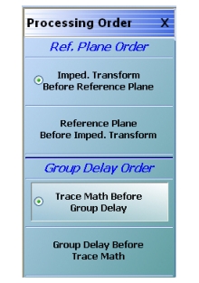
• MAIN | Measurement | MEASUREMENT | Post-Processing Order | PROCESSING ORDER
PROCESSING ORDER Menu
Reference Plane Order Button Selection Group
The two buttons in the Reference Plane area of the PROCESSING ORDER menu form a button group where selection of one button de-selects the other button.
Imped. Transform Before Reference Plane
Select sets the processing order to first process the impedance transformation and then process the reference plane data. Click Back to return to the MEASUREMENT menu.
Reference Plane Before Imped. Transform
Select sets the processing order to first process the reference plane data and then process the impedance transformation. Click Back to return to the MEASUREMENT menu.
Group Delay Order Button Selection Group
The two buttons in the Group Delay area of the PROCESSING ORDER menu form a button group where selection of one button de-selects the other button.
Trace Math Before Group Delay
Select sets the processing order to first process the trace math data and then process the group delay data. Click Back to return to the MEASUREMENT menu.
Group Delay Before Trace Math
Select sets the processing order to first process the group delay data and then process the trace math data. Click Back to return to the MEASUREMENT menu.
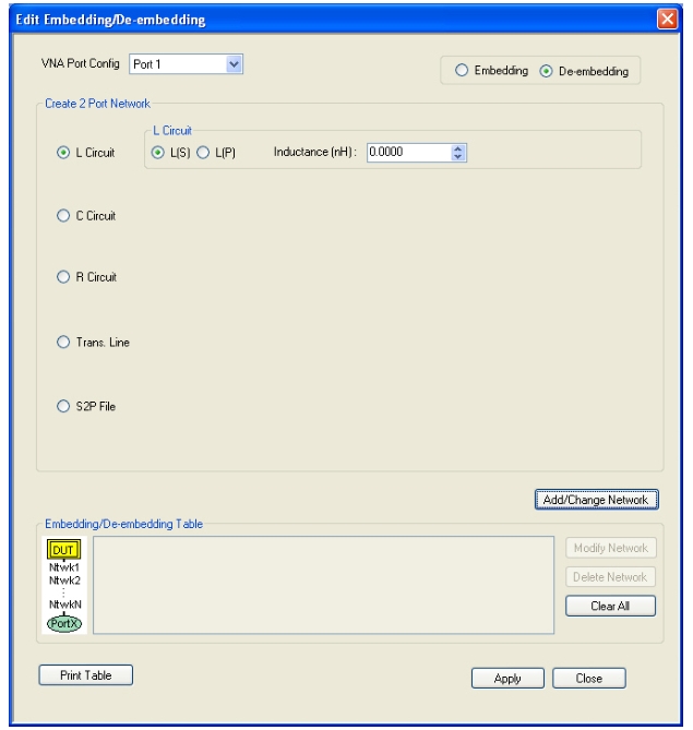
The dialog box allows user setup of the embedding/de-embedding for the DUT. The available parameters for each dialog box area are described below.
VNA Port Configuration
The available port list depends if the VNA is in 2-Port Mode or in 4-Port Mode. Port 3 and/or Port 4 are only available if the VNA is in 4-Port Mode:
• Port 1
• Port 2
• Port 3
• Port 4
• Ports 1,2
• Ports 1,3
• Ports 1,4
• Ports 2,3
• Ports 3,4
Embedding/De-embedding Radio Buttons
The configuration can be set to either embedding or de-embedding.
• Embedding
• De-embedding
Create 2 Port Network
Allows user selection of one of four types 2-Port Networks:
• L Circuit
• C Circuit
• R Circuit
• Trans. (Transmission) Line
• S2P File
Once an option above has been selected, other sub-options, described in the sections below, are available.
L Circuit Selected in Create 2 Port Network
If L Circuit is selected above in Create 2 Port Network, the L Circuit area appears with the following options:
• Radio button selections for L(S) or L(P)
• Input field for Inductance (nH)
C Circuit Selected in Create 2 Port Network
If C Circuit is selected above in Create 2 Port Network, the C Circuit area appears with the following options:
• Radio button selections for C(S) or C(P)
• Input field for Capacitance (pF)
R Circuit Selected in Create 2 Port Network
If R Circuit is selected above in Create 2 Port Network, the R Circuit area appears with the following options:
• Radio button selections for R(S) or R(P)
• Input field for Resistance (Ohms)
Trans. Line Circuit Selected in Create 2 Port Network
If Trans. Line is selected above in Create 2 Port Network, the Transmission Line area appears with the following options:
• Input field for Impedance (Ohms)
• Input field for Length (mm) or Calculator icon
• The transmission line length can be directly input in millimeters.
• If the Calculator icon is selected, the AIR EQUIVALENT LENGTH CONVERSION (from ps to mm) dialog appears. Enter the length in ps, enter dielectric constant, calculate equivalent air equivalent length, obtain the air equivalent length in millimeters. Click OK. The calculated value is entered into the Length field.
• Input field for Loss (dB/mm)
• Input field for @ Frequency (GHz)
• Input field for Dielectric constant:
• Provides menu selections for Air (1.000649), Polyethylene (2.26), Teflon (2.10), Microporous Teflon (1.69), Other.
• If other is selected, an Other input field is provided for a user-defined dielectric constant.
S2P File Selected in Create 2 Port Network
If S2P File is selected above in Create 2 Port Network, the following options are available:
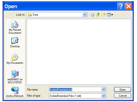
• The Load S2P file button appears. Select displays the OPEN (Display S2P File) dialog box to allow the user to navigate to a previously saved S2P file. Once a file is selected, its path and file names appears in the field next to the button.
• Swap Port Assignment check box. Normally, the network’s Port 2 will be nearer the DUT. If the Swap Port check box is selected, the port assignments are swapped.
Add/Change Network
As each network is configured, select the Add/Change Network button to add it to the Embedding/De-embedding Table. The newest configured networks are entered closest to the Test Port.
To modify or delete a network, delete the network in the Embedding/De-embedding Table. The Modify Network and Delete Network buttons become available. Use the Clear All button to clear all entries. Use the Print Table button to output a network table to a connected printer.
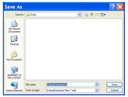
When all network changes are made, select Apply and then Close. On the EMBEDDING menu, select Save Setting to store the network configuration.
• MAIN | Measurement | MEASUREMENT | Line Type | LINE TYPE Dialog Box
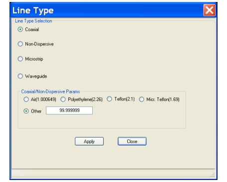
LINE TYPE Dialog Box – Coaxial, Non-Dispersive, Microstrip, or Waveguide
Line Type Selection Area
The Line Type Selection area allows user choice of four (4) different line types:
• Coaxial
• Select causes the Coaxial/Non-Dispersive Line Type Area (described below) to appear.
• Non-Dispersive
• Select causes the Coaxial/Non-Dispersive Line Type Area to appear.
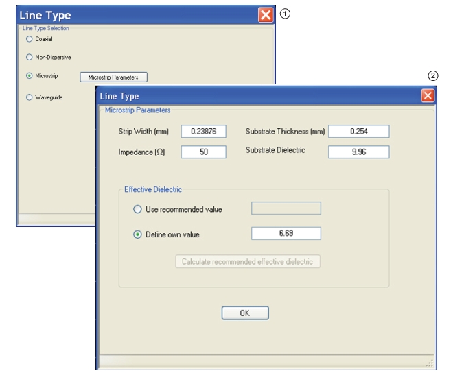
• Microstrip
• Select causes the Microstrip Parameters Area (described below) to appear.
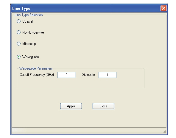
• Waveguide
• Select causes the Waveguide Line Type Area (described below) to appear.
The options and selectable parameters for each option are described in the sections below.
Coaxial or Non-Dispersive Line Types Area
If Coaxial or Non-Dispersive line type is selected, the Coaxial/Non-Dispersive Parameters area appears with a button selection group and selections of:
• Air (1.000649)
• Polyethylene (2.26)
• Teflon (2.1)
• Micr. Teflon (Microporous Teflon) (1.69)
• Other.
• If other is selected, a field appears allowing user entry of a line type dielectric parameter between 0 (zero) and 99.
Microstrip Parameters Area
If Microstrip line type is selected, the Microstrip Parameters button appears (shown below at left). Clicking Microstrip Parameters displays an additional dialog with areas for Microstrip Parameters and Effective Dielectric (shown below at right).
LINE TYPE Dialog Box – Microstrip Selected
1. Line Type Selector Area – Microstrip Selected 2. Microstrip Parameters Area – Microstrip Parameters for User-Defined Values
Microstrip Params Area
Thesystem default microstrip parameters are displayed:
• Strip width (mm): 0.23876
• Impedance (Ω): 50
• Substrate thickness (mm): 0.254
• Substrate dielectric: 9.96
To change a value, click in the field, and then enter the required parameter value.
Effective Dielectric Area
In the Effective Dielectric Area of the dialog box, select one of the two options:
• Use recommended value
• Define own value. If Define own value was selected, click in the field and enter the required dielectric value.
Click OK to close the Microstrip Parameters Area.
Waveguide Line Type Area
If Waveguide line type is selected, the Waveguide Parameters Area appears.
LINE TYPE Dialog Box -Waveguide Selected – Waveguide Parameters Area
Waveguide Parameters Area
Cut-off Frequency (GHz):
• User entry field
Dielectric value:
• User entry field
Applying Line Type Changes
1. After making a selection, you must click the Apply button to apply the changes made and then click Close.
2. On the MEASUREMENT menu, the read-only Line Type and Dielectric buttons show the entered values.
3. Clicking Close without clicking Apply abandons any changes and returns to the MEASUREMENT menu with the prior current instrument setting.
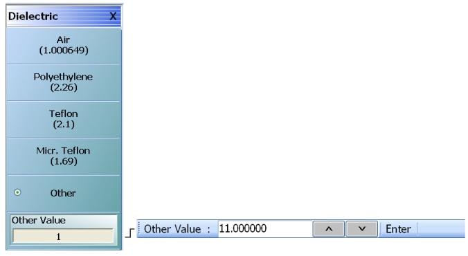
• MAIN | Measurement | MEASUREMENT | Dielectric | DIELECTRIC
DIELECTRIC Menu
The Other button must be selected to make the Other Value button and its related Field Toolbar available.
DIELECTRIC Menu Button Selection Group
The DIELECTRIC menu variably displays five (5) or six (6) buttons that are all members of a button selection group. If any single button is selected, the other buttons are deselected.
If the Other (Dielectric) button is selected, a sixth button, Other Value (Dielectric) appears at the bottom of the menu and allows the user to enter a user-defined dielectric constant.
The dielectric material selected here is displayed in the MEASUREMENT menu in the read-only Dielectric button field.
After selecting a dielectric value, click Back to return to the MEASURMENT menu.
Air (1.000649) (Dielectric)
Select sets the dielectric as air (1.000649) and de-selects Polyethylene, Teflon, Micr. Teflon, and Other.
Polyethylene (2.26) (Dielectric)
Select sets the dielectric as polyethylene (2.26) and de-selects Air, Teflon, Micr. Teflon, and Other.
Teflon (2.1) (Dielectric)
Select sets the dielectric as Teflon (2.1) and de-selects Air, Polyethylene, Micr. Teflon, and Other.
Micr. Teflon (1.69) (Dielectric)
Select sets the dielectric as Microporous Teflon (1.69) and de-selects Air, Polyethylene, Teflon, and Other.
Other (Dielectric)
Select sets the dielectric as Other (Dielectric) and de-selects Air, Polyethylene, Teflon, and Micr. Teflon. Select also displays the Other Value (Dielectric) button at the bottom of the menu.
Other Value (Dielectric)
The Other Value (Dielectric) button only appears if the Other button (above) has been selected. Once the Other Value (Dielectric) button is available, select displays the Other Value (Dielectric) field toolbar for entry of a user-defined dielectric constant.