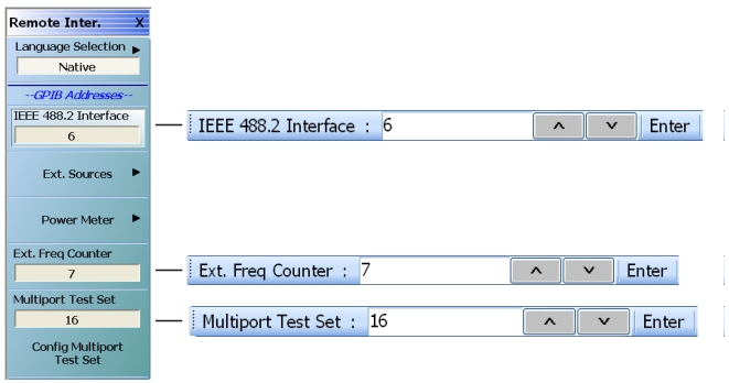
Displays the currently selected GPIB address for the VNA instrument. Select displays the IEEE GPIB field toolbar, used to establish the GPIB device number of the instrument.
• The default GPIB instrument address is 6.
• The allowable range is from 1 to 30 but must be unique for the power meter and not duplicate any other peripheral or instrument address.
Ext. Sources
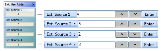
The External Sources button select displays the EXT SRC ADDR (EXTERNAL SOURCE ADDRESS) menu.
Select displays the External Frequency Counter field toolbar. Use the External Frequency Counter field toolbar to enter the GPIB device number for an optional attached frequency counter.
• The default GPIB device address is 7.
• The allowable range is from 1 to 30 but must be unique for the frequency counter and not duplicate any other address.
Multiport Test Set
Select displays the Multiport Test Set field toolbar. Use the toolbar to enter the GPIB device number for the optional Multiport Test Set.
• The default GPIB address is 16.
• The allowable range is from 1 to 20 but must be unique for the test set and not duplicate another address.
Config Multiport Test Set
Select displays the Multiport Test Set Configuration dialog box to optionally configure an attached MN469xB/C Series Multiport Test Set.
• MAIN | System | SYSTEM | Remote Interface | REMOTE INTER. | Configure Multiport Test Set | MULTIPORT TEST SET CONFIGURATION Dialog Box
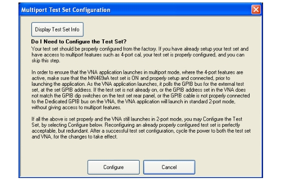
MULTIPORT TEST SET CONFIGURATION Dialog Box
Display Test Set Info Button
Select displays a dialog box with the current attached multiport test set configuration information.
Advisory Configuration Information
Your test set should be properly configured from the factory. If you have already setup your test set and have access to multiport features such as 4-port cal, your test set is properly configured, and you can skip this step.
In order to ensure that the VNA application launches in multiport mode, where the 4-port features are active, make sure that the MN469xB/C Series test set is ON and properly setup and connected, prior to launching the application. As the VNA application launches, it polls the GPIB bus for the external test set, at the set GPIB address. If the test set is not already on, or the GPIB address set in the VNA does not match the GPIB dip switches on the test set rear panel, or the GPIB cable is not properly connected to the Dedicated GPIB bus on the VNA, the VNA application will launch in standard 2-port mode, without giving access to multiport features.
If all the above is set properly and the VNA still launches in 2-port mode, you may Configure the Test Set, by selecting Configure below. Re-configuring an already properly configured test set is perfectly acceptable, but redundant. After a successful test set configuration, cycle the power to both the test set and VNA, for the changes to take effect.
Controls
The Configure button starts the configuration process. Cancel closes the dialog box and returns to the REMOTE INTER. menu.
• MAIN | System | SYSTEM | Remote Interface | REMOTE INTER. | Language Selection | REMOTE LANG.
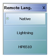
REMOTE LANG. (REMOTE LANGUAGE) Menu
REMOTE LANG. Menu Button Selection Group
The three (3) buttons of the REMOTE LANG. menu form an auto-return button selection group where the selection of one button de-selects the other two (2) buttons and returns to the REMOTE INTER. menu.
Native
Select sets the remote language to Native, de-selects the Lightning and HP8510 buttons, and auto-returns to the REMOTE INTER menu.
Lightning
Select sets the remote language to Lightning, de-selects the Native and HP8510 buttons, and auto-returns to the REMOTE INTER menu.
HP8510
Select sets the remote language to HP8510, de-selects the Native and Lightning buttons, and auto-returns to the REMOTE INTER menu.
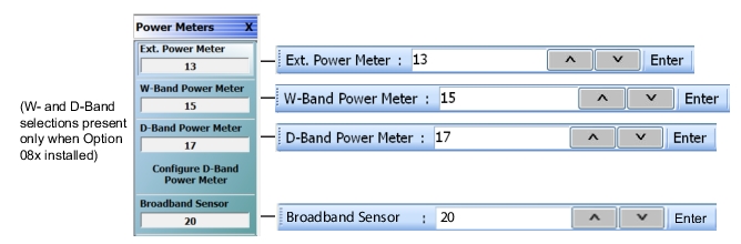
• MAIN | System | SYSTEM | Remote Interface | REMOTE INTER. | Power Meter | POWER METERS.
Power Meters Menu Showing Default GPIB Address Values
The allowable GPIB address range for the choices in this menu is from 1 to 30 but must be unique for the external source and not duplicate any other address.
Ext. Power Meter
Select displays the Ext. Power Meter field toolbar which is used to enter a GPIB device number for an external power meter.
• The default GPIB device address for external power meter is 13.
W-Band Power Meter
This selection is present only when Option 8x is installed. Select displays the W-Band Power Meter field toolbar which is used to enter a GPIB device number for a W‑Band power meter.
• The default GPIB device address for external power meter is 15.
D-Band Power Meter
This selection is present only when Option 8x is installed. Select displays the D-Band Power Meter field toolbar which is used to enter a GPIB device number for a D‑Band power meter.
• The default GPIB device address for external power meter is 17.
Configure D-Band Power Meter
This selection is present only when Option 8x is installed. Select displays D-Band Power Meter Configuration Dialog Box. Refer to D-BAND POWER METER CONFIGURATION Dialog Box.
Broadband Sensor
Select displays the Broadband Sensor field toolbar which is used to enter a GPIB device number for a broadband power sensor.
• The default GPIB device address for external power meter is 20.
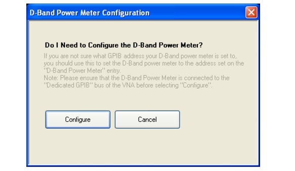
D-BAND POWER METER CONFIGURATION Dialog Box
This dialog box is available only when Option 8x is installed.
• MAIN | System | SYSTEM | Remote Interface | REMOTE INTER. | Power Meter | POWER METERS | Configure D-Band Power Meter Configuration | D-BAND POWER METER CONFIGURATION Dialog Box
D-BAND POWER METER CONFIGURATION Dialog Box
Advisory Configuration Information
If you are not sure what GPIB address your D-Band power meter is set to, you should use this to set the D-Band power meter to the address set on the “D-Band Power Meter” entry. Ensure that the D-Band Power Meter is connected to the Dedicated GPIB bus of the VNA before selecting the Configure button.
Configure Button
Select sets the D-Band power meter GPIB address to the same address as was entered on the VNA. Cancel
closes the dialog box and returns to the POWER METERS menu.