 | |
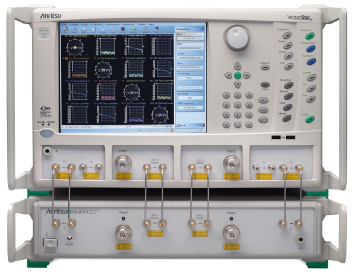
VectorStar MS4647B VNA, 10 MHz to 70 GHz, V Test Port Connectors (on top). | VectorStar MN4697C Multiport Test Set, 10 MHz to 70 GHz, V Test Port Connectors (on bottom). |
| |
VectorStar MS4647B VNA, 10 MHz to 70 GHz, V Test Port Connectors (on top). | VectorStar MN4697C Multiport Test Set, 10 MHz to 70 GHz, V Test Port Connectors (on bottom). |
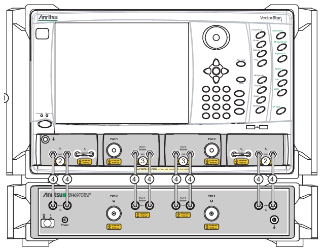 | |
1.Install the VectorStar VNA on top of MN4690C Series Multiport Test Set. 2. Remove VNA b1 and b2 loops. 3. Remove VNA Port1 Source and Port 2 Source loops | 4. Install Eight (8) provided semirigid cables between the following ports: • VNA b1 input to Multiport b1 input • VNA b1 output to Multiport b1 output • VNA Port 1 Source input to Multiport Port 1 Source input • VNA Port 1 Source output to Multiport Port 1 Source output • VNA Port 2 Source output to Multiport Port 2 Source output • VNA Port 2 Source input to Multiport Port 2 Source input • VNA b2 output to Multiport b2 output • VNA b2 input to Multiport b2 input |
 |
Index | Part Numbers | Description/Torque | Connection From | Connection To |
|---|---|---|---|---|
1 | MS469xB VNA Placed on top of MN469xC Multiport Test Set | |||
2 | 62112-141 | SMA male-male semi-rigid Tighten all connections using an 8 mm (5/16 in) torque end wrench set to 0.9 N·m (8 lbf·in). | MS464xB port labeled: b2 loop out | MN469xC port labeled: TO VNA b2 OUTPUT |
3 | 62112-140 | SMA male-male semi-rigid Tighten using an 8 mm (5/16 in) torque end wrench set to 0.9 N·m (8 lbf·in). | MS464xB port labeled: b2 loop in | MN469xC port labeled: TO VNA b2 INPUT |
4 | 62112-141 | SMA male-male semi-rigid Tighten using an 8 mm (5/16 in) torque end wrench set to 0.9 N·m (8 lbf·in). | MS464xB port labeled: P2 source loop out | MN469xC port labeled: TO VNA Port 2 Src OUTPUT |
5 | 62112-140 | SMA male-male semi-rigid Tighten using an 8 mm (5/16 in) torque end wrench set to 0.9 N·m (8 lbf·in). | MS464xB port labeled: P2 source loop in | MN469xC port labeled: TO VNA Port 2 Src INPUT |
6 | 62112-141 | SMA male-male semi-rigid Tighten using an 8 mm (5/16 in) torque end wrench set to 0.9 N·m (8 lbf·in). | MS464xB port labeled: b1 loop out | MN469xC port labeled: TO VNA b1 OUTPUT |
7 | 62112-140 | SMA male-male semi-rigid Tighten using an 8 mm (5/16 in) torque end wrench set to 0.9 N·m (8 lbf·in). | MS464xB port labeled: b1 loop in | MN469xC port labeled: TO VNA b1 INPUT |
8 | 62112-141 | SMA male-male semi-rigid Tighten using an 8 mm (5/16 in) torque end wrench set to 0.9 N·m (8 lbf·in). | MS464xB port labeled: P1 source loop out | MN469xC port labeled: TO VNA Port 1 Src OUTPUT |
9 | 62112-140 | SMA male-male semi-rigid Tighten using an 8 mm (5/16 in) torque end wrench set to 0.9 N·m (8 lbf·in). | MS464xB port labeled: P1 source loop in | MN469xC port labeled: TO VNA Port 1 Src INPUT |
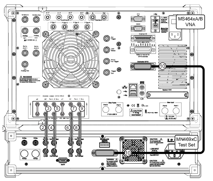
10 | 2100-1 | Rear Panel GPIB Cable 1 meter (39.3”) long | IEEE 488.2 GPIB | Dedicated GPIB |
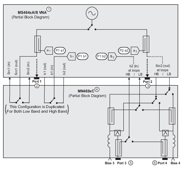 | |
The two VNA ports and the two test receivers are multiplexed to the four user ports for these measurements. The switches are of high isolation, low insertion loss, and high speed to allow for good performance even at 70 GHz. 1. VectorStar Series VNA 2. VNA Test Port 1, Port 1 Source, Port 1 a1, Port 1 b1 | 3. VNA Test Port 2, Port 1 a2, Port 2 b2 4. MN469xC Test Set 5. Test Set Port 3 and Bias Port 3 6. Test Set Port 4 and Bias Port 4 |
Note | The VNA application must be started AFTER the Test Set is connected and powered up. If the VNA application is started before the Test Set, the VNA will remain in 2-port mode and the 4-port functions will not be available. If this happens, exit the VNA application by selecting MENU BAR | File | Exit and then in the dialog box, confirm the exit. The VNA application closes to the Windows desktop. For MS464xB Series VNAs only, if returning to 100,000 point mode, restart the VNA application by selecting: Start | All Programs | VectorStar_100K | VectorStar. For MS464xB Series VNAs, if returning to 25,000 point mode, restart the VNA application by selecting: Start | All Programs | VectorStar | VectorStar. |
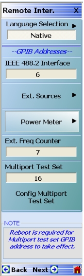 |
The REMOTE INTERFACE menu contains the External Test Set/Multiport Test Set button which accesses the addressing and configuration dialog. |