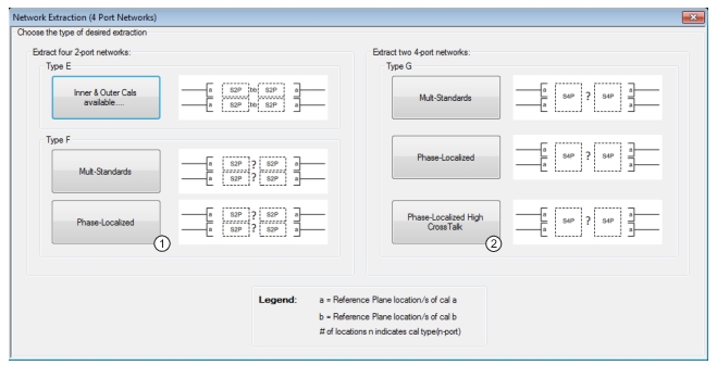
Following onto the discussion of Adapter Removal Calibrations and Network Extraction, there are additional network extraction techniques available to help find the networks for multiport de-embedding problems. The new techniques are labeled Types E, F, and G which apply for 4-Port calibrations. The original types (Types A to D) apply for 1- and 2-port configurations as before.
• Type E Network Extraction
Uses a pair of full 4-port calibrations to fully extract four S2P files describing the arms of the adapter/fixture assembly. This is a complete solution but assumes the arms of the assembly are not coupled together. This is a 4-port extension of Type C.
• Type F Network Extraction
This is a 4-port back-to-back method where four S2P files are extracted and the four arms of the adapter/fixture assembly are assumed uncoupled. As with Type D (the 2-port equivalent), match is assigned to the outer planes. Port 2 of the .s2p files is assigned to the port nearer the DUT as is consistent with the de-embedding system operation.
• Type G Network Extraction
This is a 4-Port back-to-back method where two S4P files are generated and the sides are assumed coupled (in a half-leaky sense). Measured cross-coupling is assigned to the outer planes. Port assignments on type G can be complex and the examples in the text should be noted.
• Universal Fixture Extraction
With Universal Fixture Extraction (available with Option 21 installed, and discussed in Adapter Removal Calibrations and Network Extraction of this guide), additional choices are available for Types F and G:
• Multiple Standards can be used (two lines, one line plus reflect standards, two lines plus reflect standards) instead of using just the single thru line in traditional F and G.
• The use of Phase Localization (with either a line standard or a reflection standard set) to get better estimates of network parameters based on the phase slope of the measured data.
• Phase-localized High Crosstalk is a special case of type G processing using the reflect standards, where the effects of a neighboring pair (with a high level of crosstalk between the primary pair and the neighbor) are handled more completely.
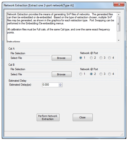
Before continuing with the new network extraction types, note that in the case of Type A, there is the additional requirement to specify where the adapter is (in the case of a multiport calibration). The added radio button selections are shown in the dialog below.
NETWORK EXTRACTION TYPE A Dialog Box
Type E Network Extraction
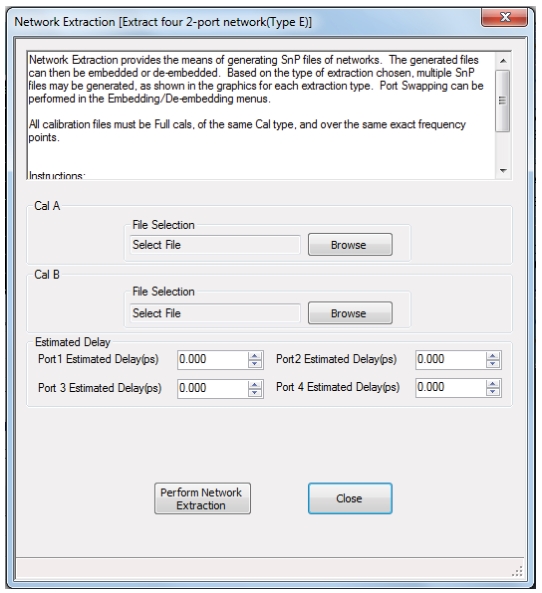
In terms of execution, Type E is very much like Type C. The two full calibration files must be specified (in this case full 4-Port calibrations). Upon execution, a dialog will appear allowing one to name the four S2P destination files. The files will be listed in order of absolute port number.
NETWORK EXTRACTION TYPE E Dialog Box
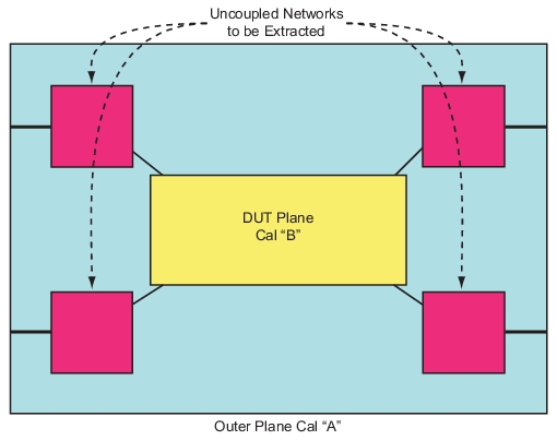
As suggested by the overall network extraction dialog, the Type E method treats the fixture as having four, uncoupled, 2-Port arms as shown below (Figure: Type E Network Extraction—Uncoupled Networks To Be Extracted). These networks are then extracted as S2P files obviously. The required level of “uncoupled-ness” depends on expected uncertainties and other losses in the networks. If the main paths were of very low loss and there was about 40 dB of coupling between arms of the fixture, there could be an added uncertainty of about 0.1 dB from ignoring that coupling with this method. If the coupling was actually 20 dB, there could be ≅ 1 dB of added uncertainty.
Type E Network Extraction—Uncoupled Networks To Be Extracted
Type F Network Extraction—without Option 21
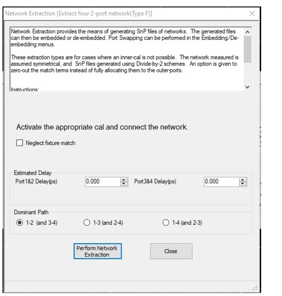
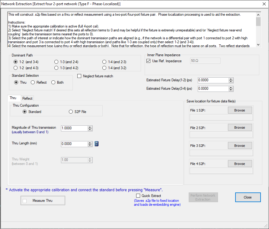
Types F and G operate much like Type D except a full 4-Port cal should be applied upon entering the dialog instead of a full 2-Port cal. The usual file definition dialog will follow. As with Type D, the check box option allows one to neglect fixture match terms instead of assigning mismatch to the outer plane.
NETWORK EXTRACTION TYPE F Dialog Box—Without Option 21
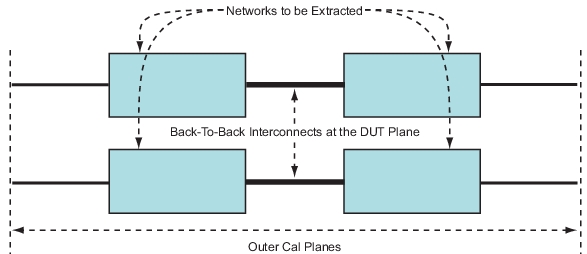
In the case of Type F, the networks are again assumed uncoupled. It is a method appropriate for the same situations as Type E except when inner calibration standards are not feasible or of reliable uncertainty. The dominant path of the fixture connection should be selected as shown in the dialog. Type F assumes the fixture looks like either independent single-ended lines or a weakly coupled differential pair. The ‘dominant’ path describes what ports are connected during the ‘thru’ step or, equivalently, what the low insertion loss paths through the fixture are.
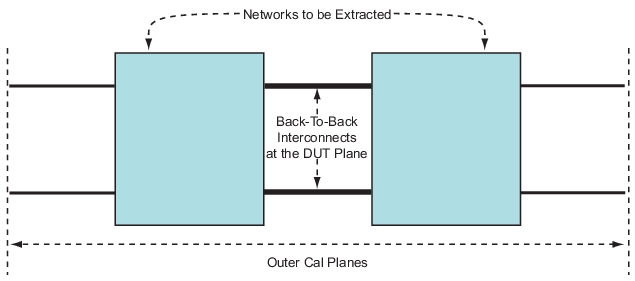
Type F Network Extraction—Back-to-Back Interconnects at the DUT Plane—Type F
Type F Network Extraction (with Option 21—Universal Fixture Extraction)
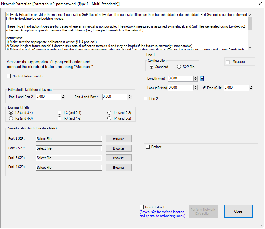
With the universal fixture extraction option (Option 21), additional Type F flexibility appears, including the use of multiple standards or phase localization as discussed for Type D previously in Adapter Removal Calibrations and Network Extraction of this guide. Of course, four files will be generated in this case (all .s2p) and, as stated earlier, it will be assumed any coupling between arms of the fixture is very weak. The non-Option -21 version of Type F differs in that only a single line standard can be used and its length must be 0.
• One line standard is always required. Using only one line will set inner plane match terms always to 0 (for all four files in this case) and side-to-side symmetry (in terms of insertion loss not outer plane match) will be assumed. The line standard must consist of paths connecting both port pairs (if 1-2(3-4) is selected as the dominant path, the line standard must connect port 1 to port 2 and must connect port 3 to port 4; see Figure: Type F Port 1/Port 2 Total Fixture Delay for Dominant Path 1-2 (and 3-4)).
• With two lines as standards, symmetry is still assumed but inner plane match will be solved for. Note that the two line lengths cannot be the same and when the phase difference between the two line lengths is 180 degrees, a singularity will occur. As an example, if line 1 is 0 and line 2 is 33 ps long (10 mm air-equivalent), a singularity will occur at 15 GHz. It is recommended to keep the excursion under 160 degrees so, for this example, 13.3 GHz would be the maximum recommended frequency. Note that at DC, there is another singularity.
• With a line and a reflect standard, symmetry is no longer forced and a coarse estimate of inner plane match is possible. The same reflect standard must be applied to all four ports during this measurement. The reflection coefficient of the standard (in magnitude and offset length) must be specified and the magnitude is allowed to be negative to allow for easy entry of a short circuit standard. Loss for line and reflect standards can be entered in dB/mm terms (that scales as sqrt(f/fref), where fref is the entered reference frequency; if fref=0, the loss is assumed to be constant with frequency).
• Using all three standard types maximizes the information possible and symmetry is not forced and a better inner plane match estimate is possible.
• As with Type D, the Quick Extract check box will disable the file entry fields and instead the files will be save to a preset hard disk location, the de-embedding engine activated, and those files loaded into the de-embedding engine. This process can be used to save time if it one desires to immediately de-embed the fixture after extracting its parameters.
• The Neglect fixture match selection overrides contributions from multiple standards and S11 and S22 will both be set to 0 in all files.
Extraction Dialog—Type F with Multiple Standards (Option 21 Enabled)
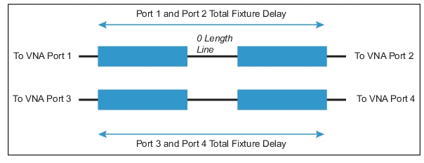
Type F Port 1/Port 2 Total Fixture Delay for Dominant Path 1-2 (and 3-4)
The configuration for the case of dominant path 1-2(3-4) with a zero length thru connected is shown here schematically.
Phase-localized F also works very much like phase-localized D except with additional files (dialog shown in Figure: Phase-localized Type F Dialog). Some of the attributes of this type:
• This method can use a thru (consisting of two interconnects as shown in Figure: Phase-localized Type F Dialog for one example configuration), a single reflect (same reflect on all four ports), two reflects (different from each other but the same two reflects used on all four ports) or a thru plus a single reflect. See the phase localized D section for more details on the standards requirements.
• The fixture delay plays a more central role as that phase length is used to localize transmission and reflection behaviors for the fixture. If 0 is entered, an automatic estimation routine will be used. The ‘top and bottom’ delays need not be equal (1 and 2 total delay vs. 3 and 4 total delay for the example port configuration of Figure: Phase-localized Type F Dialog) although they commonly are. If a reflect standard is used, individual arm fixture delays can be entered (using the ‘manual’ mode available when the reflect standard is selected.
• There are frequency list requirements to use phase-localized techniques:
• Log sweep and CW sweep are not allowed.
• If segmented sweep is used, any individual frequency step cannot deviate more than 5% from the average frequency step.
• The total fixture delay (in ns) should be at least 5/(Span of Frequency Sweep in GHz).
• The total fixture delay (in ns) should be less than 0.3/(average frequency step in GHz).
Phase-localized Type F Dialog
Type G Network Extraction
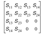
In the case of Type G, the S-parameter matrix will take on a very particular form. Ports 1 and 2 of the left network are assumed to be the outer ports and the inner ports for that network will be assigned Ports 3 and 4 for the S4P definition. Because of the match and cross-coupling assumptions, the matrix saved will take on the form below (Eq. 24‑17).
Equation 24‑17.
An eigenstructure-based solution is used to split the composite results in the upper right and lower left quadrants into the two “halves”. In most cases, there should not be convergence issues with the process unless the return loss of the structure gets very close to 0 dB. As shown, reciprocity is enforced. S11 = S22 = 0 if the check box is selected. The entire upper left quadrant is a direct map from the measurement as match and cross-coupling are assigned to the outer ports.
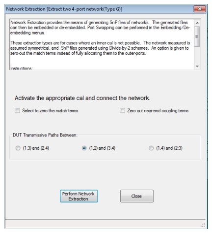
NETWORK EXTRACTION TYPE G Dialog—Without Option 21
Structurally, the measurement is the same as in Type F. The only difference is in the matrix structure of the extracted parameters.
Back-to-Back Interconnects at the DUT Plane—Type G
The port assignment on Type G is more complicated than that for the other types since there are not just 2 file assignment permutations but 24. Type G will always put the port pair that has Port 1 in it on the outside (1-2, 1-3 or 1-4, depending on how the transmissive paths are excited) and it will do this for both files. So if the transmissive paths are 1-3 and 2-4; both files will have S33=S44=0.
The embedding/de-embedding engine assigns based on port pairs and assumes the files have the same port
pair alignment. Since the port assignments between Type G and embedding/de-embedding could be completely disjointed (since the .s4p file may have been generated with a completely different setup), some care is required.
The VNA assumes a port concatenation type of numbering. Thus if the port pairs of the DUT are defined as 1-3 and 2-4, the system will expect ports 2 and 4 of the left EDE file to be connected to ports 1 and 3 of the DUT. Similarly, it will expect ports 1 and 3 of the right EDE file to be connected to ports 2 and 4 of the DUT. This is a little backward from 2-port embedding/de-embedding, but the requirement is to somewhat generally
handle the ambiguity if the pairs are not aligned at all. Particularly for the second file, there can be some
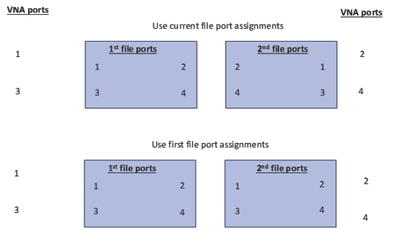
confusion about whether the ports should be swapped, but Type G offers some flexibility on port assignment to help. The Use First File Port Assignments will maintain this concatenation style and the files will then generally not need port swapping when used with the VectorStar embedding/de-embedding system. Other applications may expect a different type of alignment and, for these, the Use current file port assignmentsselection will assign the inner plane ports to the same location for the second file as for the first (i.e., both inner planes would be ports 2 and 4 in the earlier example). The relationships are shown in Figure: File Port Assignments for our example where the dominant paths are 1-2 (and 3-4) leading to outer port pairs of 1-3.
File Port Assignments
Type G Network Extraction (with Option 21—Universal Fixture Extraction)
Multi-Standard Type G Network Extraction Dialog (Option 21 Enabled)
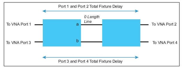
Type G Port 1/Port 2 Total Fixture Delay for Dominant Paths 1-2 (and 3-4)
For the example port configuration of 1-2 (and 3-4) dominant paths, the connection plan for a Type G extraction with a zero length thru is sketched above.
As with non-Option-21 Type G, the basic one-line-standard solution involves the concept of a matrix square root to compute the insertion loss and FEXT of each half based on the composite measurement available. The interchange of energy between insertion loss and coupled paths can be large enough that this treatment is required. The inner plane match is assumed to be zero and inner plane crosstalk (Sab in Figure: Type G Port 1/Port 2 Total Fixture Delay for Dominant Paths 1-2 (and 3-4)) is assumed to be zero. Symmetry (left-to-right in the figure) in the sense of insertion loss and FEXT (but not outer plane match) is also a required assumption with the single line standard.
The addition of another line length or a reflect standard set (or both) helps add some information. As with Type F, the addition of a second line standard allows information on inner plane match and crosstalk (assumed symmetric) and some accuracy improvements on insertion loss and outer plane match. The addition of the reflect allows symmetry to be broken and allows for a coarse estimate of inner plane match. With one line plus a reflect, inner plane crosstalk is still neglected. With all three standards, symmetry is broken, the inner plane is solved for and general accuracy improves further.
As with Types F and D, the second line must have a different length than the first line and there are the same singularities at 0 and 180 degree phase differences.
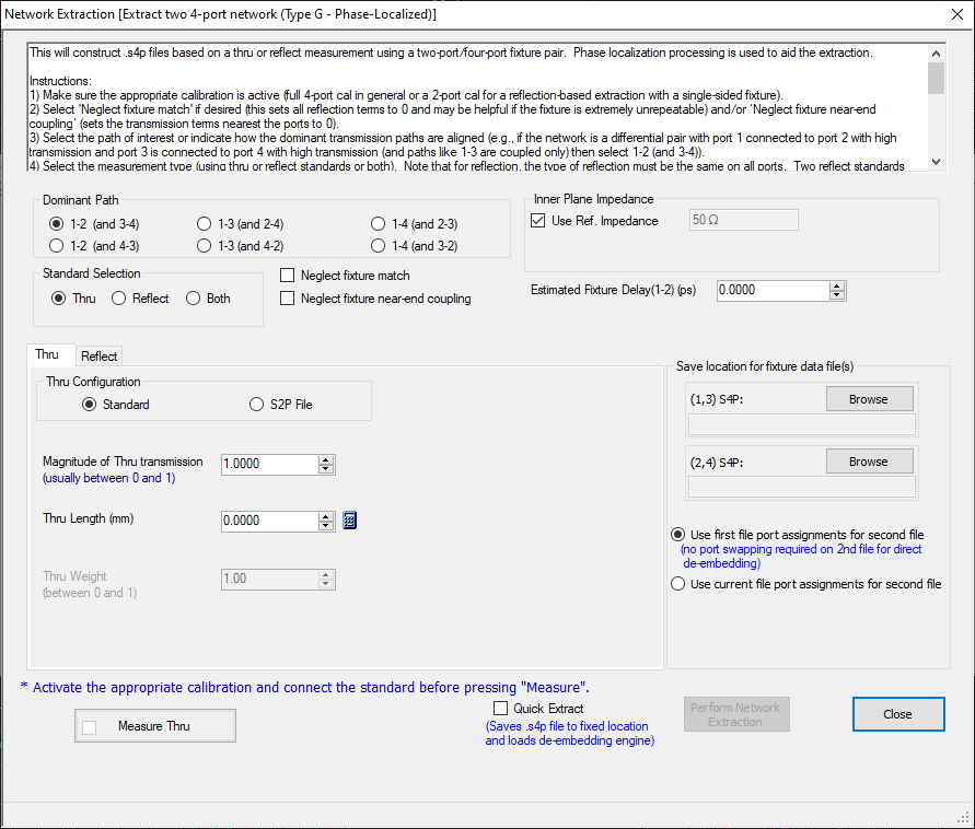
The phase-localized variant is also available for Type G and its configuration dialog is shown in Figure: Phase Localized Type G Network Extraction Dialog (Option 21 Enabled). The construct is the same as for Type F with the difference that the localization process is also used to solve for crosstalk terms. The same restrictions on frequency list apply.
Phase Localized Type G Network Extraction Dialog (Option 21 Enabled)
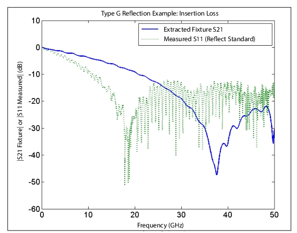
Consider an example reflection-based phase-localized Type G measurement where flush open standards are available at the inner interface. The fixture is a fairly tightly coupled differential pair with a number of internal reflection centers. The fixture length was unknown so a zero was entered for that and 1-2(3-4) was the dominant path selection. Thus the measurements needed for the extraction are based on ports 1-3 (for one half of the fixture) and ports 2-4 (for the other half (had a thru standard been selected, all 16 S-parameters would have been used—only 8 are needed when a reflect standard set is used). With the reflection standards connected, the dashed curve in Figure: Phase-localized Type G Reflection Example—Insertion Loss was obtained which can be challenging to interpret. There is a null around 18 GHz which corresponds to a coupling maximum and there are many ripples due to interactions of the reflect standard with mismatch in the fixture itself. The extracted insertion loss of the fixture half (S21) is plotted as the solid curve and one can see the null has roughly doubled in frequency since the electrical length is about half that of what was seen in the reflection measurement with open present. Note that differential insertion loss will not experience this null. The multiple reflection centers in the fixture (which are real) contribute to the residual ripple in the result. The phase localization process allowed ripple due to interaction with the reflect standard to be removed.
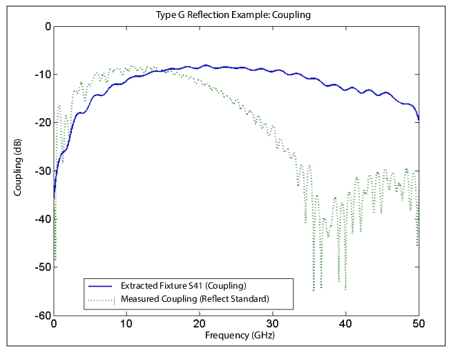
The coupling (S41) of the same fixture is plotted as the solid line in Figure: Phase-localized Type G Reflection Example—Coupling along with the input S31 measurement (with opens at both inner ports connected to outer ports 1 and 3). As expected for a coupling mechanism for a coupled line, there is a null at low frequency. There is another null in the input data (reflection standards connected) near 37 GHz. On the extracted data for S41, the null has moved out to twice that frequency due to the same change in electrical length. This illustrates the importance of processing coupling and insertion loss together on fixtures such as this. Treating them independently would result in the null remaining at the now non-physical frequency of ~37 GHz. As with the previous figure, the residual ripple is due to physical reflection centers within the fixture interacting.
Phase-localized Type G Reflection Example—Insertion Loss
The solid curve denotes the extracted insertion loss profile (single-ended) for the example fixture and the dashed curve is some of the measured data (with opens at the inner plane) used to compute the solid curve.
Phase-localized Type G Reflection Example—Coupling
The coupling for this fixture (extracted S41 and measured (with opens) S31) are plotted in this figure. Note that the null has moved out as expected.
As with phase localized D and F, there are some standards permutations allowed. Two reflect standards (different from each other but the same reflects are used on all ports) can be used where the added information is used to refine transmission and crosstalk results (and inner plane match to some degree). Also, a thru (in the sense of two port interconnects) can be used in conjunction with a reflect standard (same on all ports) where the additional information is used to refine knowledge of the match terms in particular. A weighting term is provided (range 0 to 1 where 1 indicates the thru measurement is used more heavily and a 0 means the reflect measurement is used more heavily). It is not allowed to use a thru with two reflects as the amount of information increase was found to be diminishing.
Type G Network Extraction Phase-localized High Crosstalk (with Option 21—Universal Fixture Extraction)
A special case of type G processing using the reflect standards is also provided where the effects of a neighboring pair (with a high level of crosstalk between the primary pair and the neighbor) are handled more completely. This can be an important problem since, when those crosstalk levels are high, how the neighboring pair is terminated will change the loading on the primary pair and, if that loading is not the same at characterization time and when the path is being used, additional uncertainty can be incurred. The approach is to characterize both the primary pair and the neighbor at the same time (using reflect standard-based phase localization) and create a complete model of the interactions. Then, different loading levels (expressed via reflection coefficients or .s1p files) can be applied to the model and the .s4p of the primary pair generated for that level of neighbor loading. As might be expected, if the crosstalk levels between the primary and neighbor are low, this method provides no real benefit and the regular methods can be used. The level of crosstalk of relevance varies with the situation
• Insertion loss effects are normally visible only on lower loss lines and are small unless the crosstalk is very high (> –10 dB) but can be on the scale of tenths of a dB for slightly lower levels.
• If intra-pair coupling levels are on the same order as the crosstalk, considerable dependence may be observed on those primary pair coupling parameters.
• If the line losses are low and the lines well-matched (relative to the crosstalk levels), variations in match can be observed.
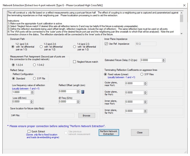
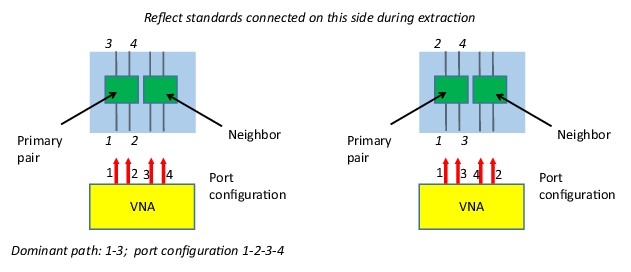
The configuration dialog for this special method is shown in Figure: Phase-localized High Crosstalk Type G Network Extraction Dialog (Option 21 Enabled) and has many of the same attributes as the usual phase localized G (dominant path selection, reflection definition for the inner plane, match term and file name selections, fixture delay estimates and inner plane impedance). The connection of the VNA to the fixture assembly during characterization is different in that one pair of ports is used for the primary pair and the other pair of ports is used for the neighbor (instead of being used for the other half of the fixture; thus this method only characterizes on ‘half’ of a fixture per run). The connection configuration is illustrated in Figure: Two different connection configurations for the characterization measurement. for two different port configurations and the connections here must be selected under Measurement Port Assignment.
The italicized port numbers in Figure: Two different connection configurations for the characterization measurement. denote how the port numbers will be assigned in the output .s4p file. As with other network extraction methods, this comes from the dominant path selection, so one should check that selection carefully. Since the embedding/de-embedding system does allow port swapping, the arrangement can be changed later. The red arrows in the figure represent the cables from the VNA with the port numbers indicated. As with other type G methods, a coaxial calibration is assumed to exist (at reference planes to be connected to the outer ports of the fixture) and the reference plane should effectively be at the tips of those arrows.
Phase-localized High Crosstalk Type G Network Extraction Dialog (Option 21 Enabled)
Two different connection configurations for the characterization measurement.
As Figure: Two different connection configurations for the characterization measurement. pictorially suggests, the characterization will result in a .s8p file which incorporates all of the crosstalk behavior (under the phase localized assumptions so the same length requirements apply as for regular phase-localized G). When Perform Network Extraction is selected, this .s8p file is generated and, if desired, can be used elsewhere. It is saved as a fixed file name at c:\ProgramData\Anritsu Company\AC-VNA-VectorStar\Dependencies\NetworkExtraction with file names of the form Ch1_phaseLocalizedTypeGCrossTalk.s8p (and the ‘1’ would be replaced by the channel number for files generated from other channels). Every time this method is used, that file is overwritten for the currently active channel.
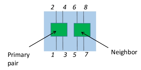
If one does want to use the .s8p file externally, note that the port assignments for this file are fixed (see Figure: Port Assignments for .s8p File) and will not change based on settings in the dialog box. Internally, the measurements are all mapped to a fixed port assignment for processing. When the .s8p data is used to create the final .s4p file for the primary pair, the mapping is undone. This mapping process is invisible to the user unless the .s8p file is used externally.
Port Assignments for .s8p File
This information is only relevant if the .s8p file is used externally to the VectorStar application.
The .s8p file itself is difficult to use in practice and the intent of the feature is to assess the loading effects of the neighbor and how they can affect the primary pair. This method’s primary objective is to create a .s4p file for the primary (and that is the file name entered in the dialog) for a given loading of the neighbor. This is where the reflection coefficient entry in the lower right of Figure: Phase-localized High Crosstalk Type G Network Extraction Dialog (Option 21 Enabled) come into play. The reflection coefficients of the loads attached to the neighbor pair (constant with frequency and real only) can be entered here or .s1p files can be loaded for those loading elements in order to include frequency dependence and complex values. Recall that, by definition, the .s8p file will describe the primary pair characteristics when the neighbor is terminated perfectly (reflection coefficient equals zero). The first reflection coefficient entry is assigned to the outer plane neighbor port closest to the primary pair and the second entry is assigned to the other neighbor outer plane port. Similarly, the third entry corresponds to the inner plane neighbor port closest to the primary pair and the fourth entry belongs to the final (further away) inner plane neighbor port.
Now, it may be desirable to generate primary-pair .s4p files for several different neighbor loading states and it could be useful to not have to repeat the characterization every time. This is where the saved .s8p file can be used along with the Use Previous Network Measurement checkbox. If that box is checked, another measurement will not be taken but the existing .s8p file will be used with the current reflection coefficient/.s1p definitions for the neighbor pair terminations. This checkbox is only available if a .s8p file has been generated and is present in the directory described earlier (e.g., after preset, there will not be such a file).
As an example of the performance of this method, a tightly coupled set of lines (10–20 dB coupling between pairs over most of the frequency range) was analyzed. It was desired to know the primary pair S-parameters for fixture de-embedding under three different loading conditions corresponding to different ways that the fixture would be used with DUTs.
1. Good terminations (near 50 ohms single-ended). A fixed reflection coefficient of 0 was entered.
2. Opens. A fixed coefficient of 1 was entered.
3. Near shorts. A .s1p file was used with an average reflection magnitude of 0.99 and a high frequency phase of 150 degrees (179 degrees at low frequency).
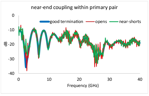
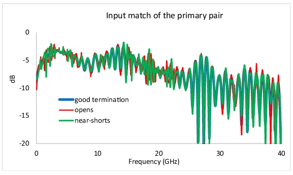
Since the crosstalk was –10 to –20 dB and intra-pair coupling was only a few dB tighter on average, noticeable impact on near-end intra-pair coupling (see Figure: Fixture Near-end Coupling (Primary Pair) for Different Neighbor Loading Levels) was expected. Indeed, the variation exceeded several dB in places. It is interesting to note that the added ripple present for the more reflective terminations is nearly 180 degrees out of phase between the open case and the near-short case and this follows intuitively. The input match (Figure: Fixture Mismatch (Primary Pair) for Different Neighbor Loading Levels) also shows some variation that is dependent on the crosstalk level at a given frequency, the mismatch level and the location along the line that is the dominant contributor to mismatch. Insertion loss for this particular example showed 0.3 dB peak variation with the neighbor terminations tried.
Fixture Near-end Coupling (Primary Pair) for Different Neighbor Loading Levels
The solid curve denotes the extracted insertion loss profile (single-ended) for the example fixture and the dashed curve is some of the measured data (with opens at the inner plane) used to compute the solid curve.
Fixture Mismatch (Primary Pair) for Different Neighbor Loading Levels
To summarize, the high crosstalk version of phase localized type G is most valuable when there is a differential pair (the neighbor) that is tightly coupled to the differential pair to be extracted and the terminations of the neighbor may vary between different DUT measurements and/or between characterization time and DUT measurement time. The loading effects of the neighbor are parameterized against neighbor terminations by this method to make it easier to generate more accurate de-embedding files for the primary pair.
Sequential Extraction (Peeling)
Another method of network extraction involves modeling the network as a collection of lumped elements. This is particularly popular for electrically small structures (e.g., on-wafer) of those with runs of transmission line punctuated by electrically small structures (e.g., PC boards with isolated vias in transmission lines).
Procedurally, this method works on one lumped element at a time. This method is covered in more detail in Sequential Extraction—Peeling (with Option 21) in Adapter Removal Calibrations and Network Extraction, but the concept is similar for 2-port and 4-port constructions. When the lumped defect/element is treated as a simple series impedance or shunt admittance, a .s2p file is generated that can be de-embedded to allow one to get at the next element. For the 4-port case, an impedance coupling two lines can also be treated in which case a .s4p file is generated. Also transmission line segments can be separately de-embedded to get between lumped defect areas. The process is based on reflection measurements only in the case of 2-port analysis and mixed-mode reflection measurements in the case of 4-port analysis (which one can think of as a 2-port measurement within a 4-port context). A full calibration incorporating the relevant port(s) must be in force.
Uncertainties and Sensitivities
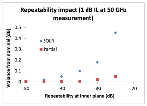
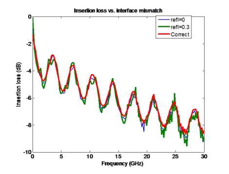
Much was covered in Adapter Removal Calibrations and Network Extraction on the sensitivity and uncertainty issues with a number of network extraction methods and little changes in the 4-port cases. Type E is just an extension of Type C in requiring two full-port calibrations and hence being sensitive to all calibration standards and measurements. Types F and G are both partial information techniques like Type D and attempt to get solid estimates of insertion loss (and crosstalk in this case) in the presence of possibly poor repeatability and will ignore inner plane match issues. To emphasize the repeatability importance to this selection process, a comparison is shown in Figure: Plot of Repeatability Impact for a Partial Information Technique (1 of 2). Inner plane match is ignored also in the 4-port variants and can have an impact if sufficiently poor as suggested in Figure: Effect of Inner Match on a Type F or G Extraction. For this example fixture, a Type E method would have experienced errors exceeding 3 dB due to the difficulty of making any reasonable reflection standards at a geometrically complicated interface.
Plot of Repeatability Impact for a Partial Information Technique (1 of 2)
A plot of repeatability impact for a partial information technique (like methods D, F, and G) is shown here compared to a conventional calibration.
Effect of Inner Match on a Type F or G Extraction
The effects may be noticeable but the alternative approaches may be much worse depending on the geometry and media.
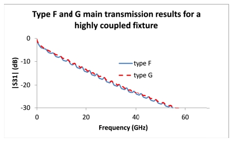
As stated earlier, the main difference between Types F and G is in handling coupling between fixture arms. Type F treats each of the 4 arms as an independent 2-port network while Type G treats each of the two macro ‘sides’ of the fixture as a 4-port network and hence can include coupling terms. As might be expected, the difference between the two methods becomes apparent with a coupled fixture and a measurement example is shown in Figure: Difference in Measurement Performance for Type F and G when the Fixture Arms are Tightly Coupled for a structure with ~10–20 dB coupling levels.
Difference in Measurement Performance for Type F and G when the Fixture Arms are Tightly Coupled
The difference in measurement performance for Type F and G are shown here when the fixture arms are tightly coupled. The results generally overlay when the coupling is loose.