Almost all of the concepts discussed elsewhere in this chapter also apply to broadband and mmWave measurements performed using variants of the ME7838x system based on the 3739 family of test sets. The software implications are minimal: all of the items discussed elsewhere in this chapter still apply. The hardware is, however, obviously configured somewhat differently. The purpose of this section is to cover the hardware configurations and the measurement implications.
Broadband/mmWave Setup Based on the 3743x/3744x/MA25XXXA Modules
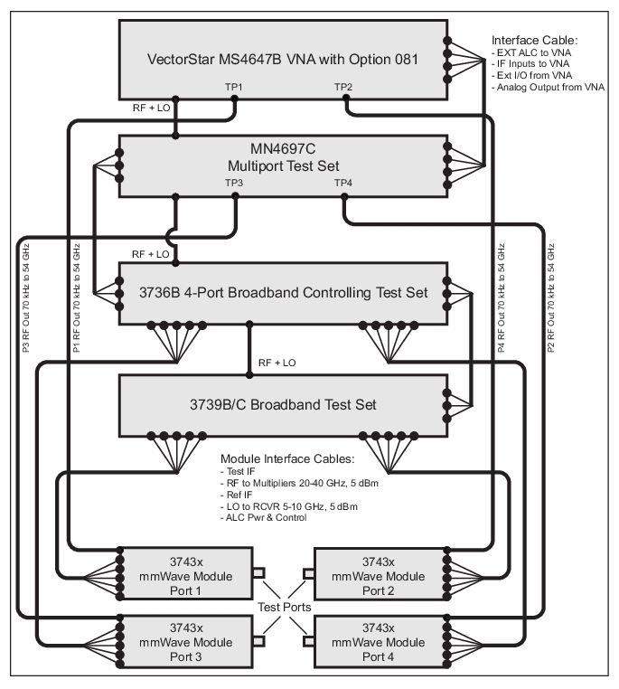
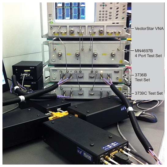
Using the modules listed above, the 3739x test set, the 3736B controlling test set, and a standard MN4697B/C four port test set with the VNA, a full 4-port system can be created.
With regard to the 373x mmWave tests used in 4-port systems, we must introduce the concept of the 'controlling' test set (3736B). The other 3739x test set (for the other two modules) acts as a controlled test set and can be a regular, unmodified test set as used in a 2-port system. The 3736B controlling test set mediates control signals between the VNA and the modules, thus making the upgrade process from a 2-port system simpler. In all cases, the 3736B controlling test set feeds modules for ports 3 and 4 while the 3739x test set feeds modules for ports 1 and 2.
• use a direct drive path (from the 4-port test set in this case) to provide low frequency stimulus
• receive RF from a test set for high frequency stimulus
• receive an LO for all conversions within the module (>30 GHz)
• return IFs to the VNA for those local conversions
• have a control cable for power, control, and leveling signals
The only real difference is some multiplexing and control manipulation that now occurs in the 3736B controlling test set. From the point-of-view of the VNA and the user, this multiplexing is essentially invisible.
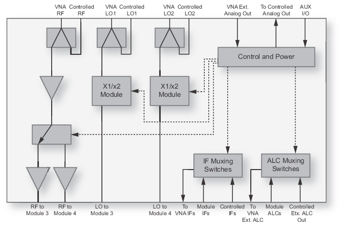
On the RF and LO side, there are splitters used to distribute the signals and there is enough power margin that available port power and conversion stability are not affected. The transfer switches within the test sets are configured to maintain isolation for all S-parameters. To help understand this distribution, the internal block diagram of the 3736B test set is shown in Figure: 3736A/B Controlling Test Set Block Diagram.
ME7838A4/A4X—Four-port Broadband System with MN4697C Multiport Test Set
Other ME7838x4 systems are the same except for the use of different modules.
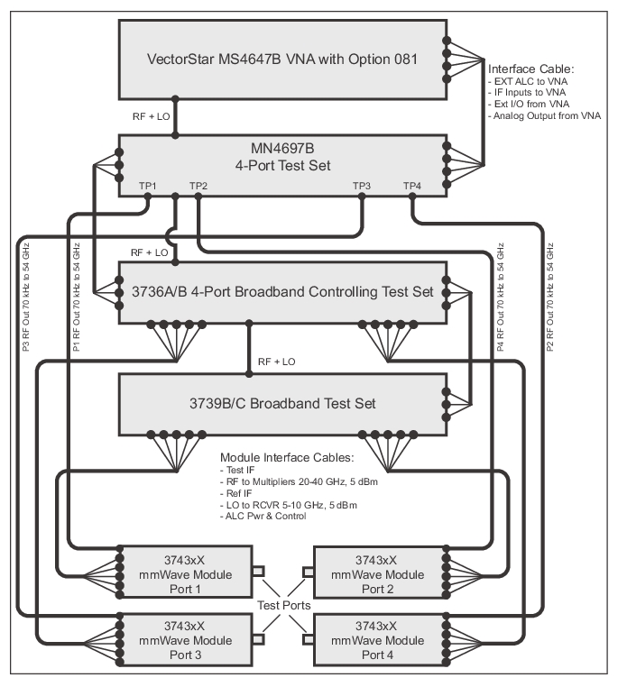
ME7838A4/A4X—Four-port Broadband System with MN4697B Multiport Test Set
Other ME7838x4 systems are the same except for the use of different modules.
RF and LOs come from the Option 8x connectors on the VNA front panel. A split portion of these signals is used in the controlling test set and a split portion is sent to the standard 3739x test set. IFs and ALC detection signals are returned from the controlled test set, multiplexed with those from the controlling test set, and then returned to the VNA. Additional multiplexing and LO multiplier sections are shown in this test set that are used for higher mmWave bands, as will be discussed shortly. The MN4697B/C used to provide additional control signals to the controlling test set test set in most situations via a separate DB9 connector (now these system are controlled with additional signals in the main rear panel broadband/mmWave harness; if the system does not come with a DB9 cable, the revised harness is used). These signals are the port configuration logic signals normally associated with any 4-port measurement, so they are needed to control signal separation in the mmWave modules as well.
3736A/B Controlling Test Set Block Diagram
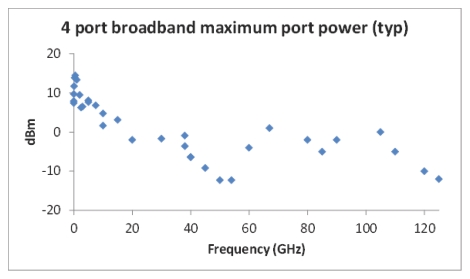
The performance of the system is very similar to that seen in the 2-port broadband system discussed in Broadband/mmWave Measurements (Option 7, Option 8x). Because of the path loss through the 4-port test set, there will be less power available towards the top part of the direct drive range (54 GHz), but the higher frequency maximum power levels will be the same. A typical plot of maximum port power is shown in Figure: Broadband 4-Port System Maximum Port Power (typical). There is dynamic range reduction by about 6 dB at 54 GHz because of this power reduction. In addition, there is a few dB dynamic range reduction just below 30 GHz (and proportionately less at lower frequencies) due to some added loss in the baseband receiver path.
Broadband 4-Port System Maximum Port Power (typical)
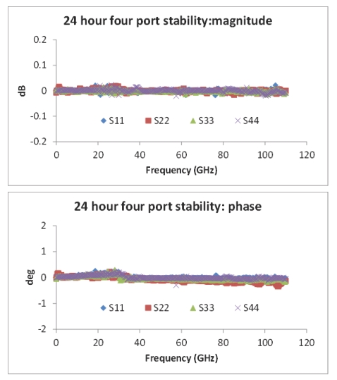
Measurement stability remains excellent with the 4-port broadband system and example plots are shown in Figure: Broadband 4-Port System Stability (typical) over a 24 hour period. In this case, the data was normalized at the start of the experiment and the deviations from those values over the 24 hours are plotted. As might be expected, the stability in a 4-port measurement is even more cable-sensitive than is that in a 2-port measurement. Minimizing cable runs (but not at the expense of too small a bending radius) and external temperature influences can help.
Broadband 4-Port System Stability (typical)
The calibration choices remain the same as for traditional 4-port system although in practice, there will be more SSSR related calibrations performed with the mmWave modules. The algorithmic choices were described in earlier chapters. Hybrid and merged calibrations will also be used more often in a broadband environment. The main reminder is that for both hybridization and merging operations, the underlying calibration types must be the same (i.e., full 2-port calibrations combined into a hybrid 4-port calibration or a merge of two full-4-port calibrations).
Measurement uncertainties follow the discussions presented earlier in this chapter. In general, there are no changes from the broadband 2-port case except for certain DUTs with many connected ports and certain high loss situations at lower frequencies (in which case the load match contributions of the many non-direct ports can start to become significant).
The mmWave banded systems based on the 3744A modules are constructed essentially the same way as described here except the connections from the 4-port test set to the modules do not exist (that provide baseband stimulus and response paths). The MN4697C test set may not be required for these systems. Contact Anritsu for more information.
Although the examples above did not cover it, the other 4-port ME7838x4/x4X broadband systems operate similarly to the ME7838A4.
mmWave Systems Based on OEM Modules
Much as high frequency 2-port systems are possible based on OEM mmWave modules operating to 1 THz and beyond, 4-port systems can be constructed in exactly the same way. The control paths are identical to those discussed previously, except there are no connections from the 4-port test set directly to the modules and there are no control cables directly to the modules.
Example Four-port mmWave Configuration with 330 to 500 GHz WR-2.2 Modules
The performance of these systems is essentially the same as for the corresponding 2-port cases since there are no baseband paths involved. The RF and LO drive levels are such that saturation is maintained so port power and measurement stability will be maintained as well. Calibration choices are unchanged from the other 4-port situations, although waveguide calibrations will be predominantly used and merges are less likely. The waveguide-based reciprocal choices (often SSLR) will be helpful if the DUT configuration requires waveguide bends for connections. Uncertainties follow the discussion earlier in this chapter where the only analysis modifications occur on multiply-connected DUTs.