• MAIN | System | SYSTEM | Setup | SETUP | Misc. Setup | MISC. SETUP | SnP Files Setup | SnP SETUP Dialog
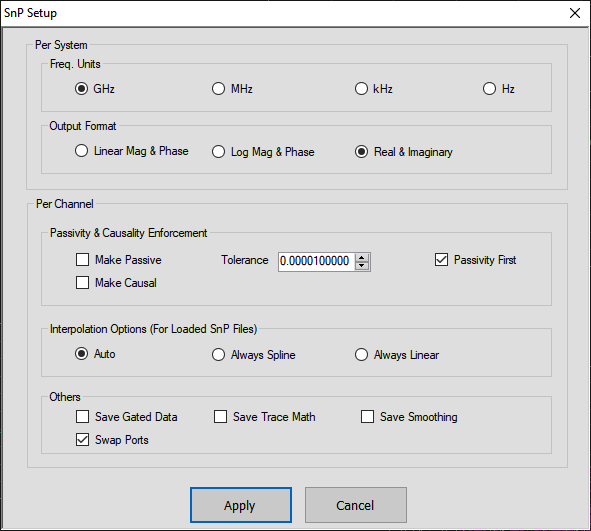
SnP FILES SETUP Dialog – 2-Port VNAs
Per System Area:
• Frequency Units Area Selections:
• GHz
Select sets the units for the SnP file output to GHz.
• MHz
Select sets the units for the SnP file output to MHz.
• kHz
Select sets the units for the SnP file output to kHz.
• Hz
Select sets the units for the SnP file output to Hz.
• Output Format Area Selections:
In the Output Format area of the menu, the three (3) radio buttons form a group where the selection of one de-selects the other two.
• Linear Magnitude & Phase
Select sets the data file output format to record linear magnitude and phase information.
• Log Magnitude & Phase
Select sets the data file output format to record log magnitude and phase information.
• Real & Imaginary
Select sets the data file output format to record real and imaginary information.
Per Channel Area:
• Passivity and Causality Enforcement Area:
• Make Passive Checkbox
When selected, during the .SnP file save process, the following occurs:
At each frequency point, evaluates the eigenvalues of the S matrix. If the largest magnitude of eigenvalues is <1, does nothing and proceeds to the next frequency. If the largest exceeds 1, scales all S-parameters at that frequency in a self-consistent way to ensure the maximum eigenvalue magnitude is <1.
• Passivity Tolerance
Describes how close to 1 (in magnitude) the largest eigenvalue is allowed to get before action is taken (1-sqrt(tolerance) is the limit used). This may need to be changed if the VNA data is being used in a simulator/model analyzer with a different numerical definition of passivity (based on resolution, convergence requirements, etc.). The default value is 0.00001. Generally values are not used outside the range of 0.0000001 to 0.001.
• Passivity First Checkbox
When both 'Make Passive' and 'Make Causal' boxes are checked, this checkbox determines which process is done first. The default is to perform 'Make Passive' first.
• Make Causal Checkbox
When selected, during the .SnP file save process, the following occurs:
A transform process is applied on each parameter to ensure minimal energy is present in the signal before the equivalent time t=0. Kramers-Kronig relations are enforced which does require reasonably fast decay of the parameter magnitude with frequency and certain aspects of analyticity. See the Calibration and Measurement Guide for more information. It is recommended to only use this function if there are observed problems when using saved data in a time domain simulator.
• Interpolation Options (for Loaded SnP Files) Area
• Choose between Auto, Always Spline (default), and Always Linear.
• Others Area:
• Save Gated Data Checkbox
When toggled ON, saves gated data into the SnP file. The Default value is OFF. This option is not available in power sweep modes.
• Save Trace Math Checkbox
When toggled ON, saves trace math to the applicable .SnP file. The Default value is OFF.
• Save Smoothing
When an .snp file is saved with " Save Smoothing enabled, a comment line ("! Smoothing applied") will be added to the generated .snp file, indicating smoothing is applied.
• Swap Ports
When toggled ON, the port functions are swapped. Swaps the s2p file on the given channel. The data will be swapped during the save process. The saved .snp data to be configured in a different orientation from how it was measured (in terms of which ports of the VNA were connected to which ports of the DUT).
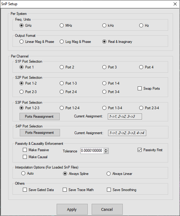
SnP SETUP Dialog Box – 4-Port VNAs
The controls in the SnP SETUP dialog box allow for configuration of file output for all SnP file types.
• MAIN | System | SYSTEM | Setup | SETUP | Misc. Setup | MISC. SETUP | SnP Files Setup | SnP SETUP Dialog Box
SnP SETUP Dialog Box – 4-Port VNAs
Per System Area
• Frequency Units Area Selections:
• GHz
Select sets the units for the SnP file output to GHz.
• MHz
Select sets the units for the SnP file output to MHz.
• kHz
Select sets the units for the SnP file output to kHz.
• Hz
Select sets the units for the SnP file output to Hz.
• Output Format Area Selections:
In the Output Format area of the menu, the three (3) radio buttons form a group where the selection of one de-selects the other two.
• Linear Magnitude & Phase
Select sets the data file output format to record linear magnitude and phase information.
• Log Magnitude & Phase
Select sets the data file output format to record log magnitude and phase information.
• Real & Imaginary
Select sets the data file output format to record real and imaginary information.
Per Channel Area
• S1P Port Selection
On a per-channel basis, allows the S1P single port to be selected as:
• Port 1
• Port 2
• Port 3
• Port 4
• S2P Port Selection
On a per-channel basis, allows the S2P port pair to be selected as:
• Port 1-2
• Port 1-3
• Port 1-4
• Port 2-3
• Port 2-4
• Port 3-4
• Swap Ports
When toggled ON, the port functions are swapped. Swaps the s2p file on the given channel. The data will be swapped during the save process. The saved .snp data to be configured in a different orientation from how it was measured (in terms of which ports of the VNA were connected to which ports of the DUT).
• S3P Port Selection
On a per-channel basis, allows the S2P port triad to be selected as:
• Port 1-2-3
• Port 1-2-4
• Port 1-3-4
• Port 2-3-4
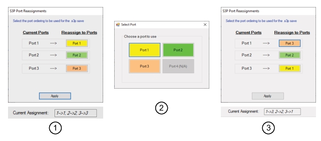
• Port Reassignment
Swaps the s3p file on the given channel. The data will be swapped during the save process. The saved .snp data to be configured in a different orientation from how it was measured (in terms of which ports of the VNA were connected to which ports of the DUT).
2. Press a colored port button to display the Select Port dialog
3. Press a colored port button in the Select Port dialog. This is new port to swap with the Current Port.
4. Repeat the S3P Port Reassignments again to make the change for the ported swap (i.e swap 1 to 3 also requires a swap of 3 to 1).
5. Press Apply. The Current Assignment in the SnP dialog will display the new port swap assignments.
S3P Port Reassignments
1. S3P Port Reassignment Dialog (before swap)
2. Select Port dialog
3. S3P Port Reassignment Dialog (after Swap)
S4P Port Selection
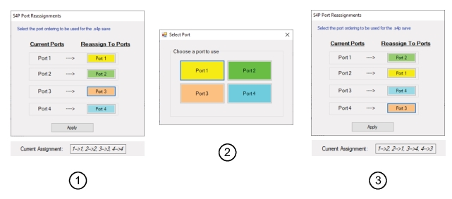
• Port Reassignment
Swaps the s4p file on the given channel. The data will be swapped during the save process. The saved .snp data to be configured in a different orientation from how it was measured (in terms of which ports of the VNA were connected to which ports of the DUT).
2. Press a colored port button to display the Select Port dialog
3. Press a colored port button in the Select Port dialog. This is new port to swap with the Current Port.
4. Repeat the S4P Port Reassignments again to make the change for the ported swap (i.e swap 3 to 4 also requires a swap of 4 to 3).
5. Press Apply. The Current Assignment in the SnP dialog will display the new port swap assignments.
S4P Port Reassignments
1. S4P Port Reassignment Dialog (before swap)
2. Select Port dialog
3. S4P Port Reassignment Dialog (after Swap)
• Passivity & Causality Enforcement
• Make Passive Checkbox
When selected, during the .SnP file save process, the following occurs:
At each frequency point, evaluates the eigenvalues of the S matrix. If the largest magnitude of eigenvalues is <1, does nothing and proceeds to the next frequency. If the largest exceeds 1, scales all S-parameters at that frequency in a self-consistent way to ensure the maximum eigenvalue magnitude is <1.
• Passivity Tolerance
Describes how close to 1 (in magnitude) the largest eigenvalue is allowed to get before action is taken (1-sqrt(tolerance) is the limit used). This may need to be changed if the VNA data is being used in a simulator/model analyzer with a different numerical definition of passivity (based on resolution, convergence requirements, etc.). The default value is 0.00001. Generally values are not used outside the range of 0.0000001 to 0.001.
• Passivity First Checkbox
When both 'Make Passive' and 'Make Causal' boxes are checked, this checkbox determines which process is done first. The default is to perform 'Make Passive' first.
• Make Causal Checkbox
When selected, during the .SnP file save process, the following occurs:
A transform process is applied on each parameter to ensure minimal energy is present in the signal before the equivalent time t=0. Kramers-Kronig relations are enforced which does require reasonably fast decay of the parameter magnitude with frequency and certain aspects of analyticity. See the Calibration and Measurement Guide for more information. It is recommended to only use this function if there are observed problems when using saved data in a time domain simulator.
• Interpolation Options (for Loaded SnP Files) Area
• Choose between Auto, Always Spline (default), and Always Linear.
• Others Area:
• Save Gated Data Checkbox
When toggled ON, saves gated data into the SnP file. The Default value is OFF. This option is not available in power sweep modes.
• Save Trace Math Checkbox
When toggled ON, saves trace math to the applicable .SnP file. The Default value is OFF.
• Save Smoothing
When an .snp file is saved with " Save Smoothing enabled, a comment line ("! Smoothing applied") will be added to the generated .snp file, indicating smoothing is applied.