When monitoring traffic over the CPRI link, the Anritsu test instrument will extract the IQ data and process the signal into data points to be plotted on the instrument screen. The CPRI parameters described in the following sections are needed for the CPRI Analyzer to process and display the data correctly. Note that configurations may be different for the uplink and downlink. The uplink signal represents mobile phone LTE data. The downlink signal is the display of BBU LTE signals to RRH.
All CPRI IQ data is at baseband frequency. To allow the CPRI signal to move off center (pan), turn the Center Frequency Reference setting on and adjust the center frequency to a different value. Depending on the value entered, this may automatically adjust the frequency span, as there cannot be panning without zooming. Refer to Freq Menu.
Note
Some CPRI parameter settings like line rate, LTE carrier bandwidth, and AxC group and port selections for traces can be selected both in the CPRI configuration and the PIM Over CPRI configuration (Option 754 only). Refer to PIM Over CPRI Configuration Settings.
When saved and applied to PIM measurements from the PIM Aid configuration dialog, these settings remain in effect after you exit PIM Over CPRI mode and change to CPRI Spectrum mode, for example.
Line Rate
Line Rate is the speed of the CPRI link. Table: CPRI Line Rates lists the selectable line rates and associated rate numbers, 1 through 8. The 10 Gbit/s line rate is available with firmware version 2.6 and later. If needed, refer to your instrument User Guide for firmware upgrade instructions.
The instrument display shows the line rate on the left side of the screen. On models with dual SFP ports, the top value is the line rate of SFP Port 1 and the bottom value is SFP Port 2 line rate. Refer to SFP Port Config Menu.
CPRI Line Rates
CPRI Rate
Line Rate (Mbit/s)
1
614.4
2
1228.8
3
2457.6
4
3072.0
5
4915.2
6
6144.0
7
9830.4
8
10137.6
CPRI Bandwidth
This is the bandwidth of the LTE carrier that is transmitted via CPRI. Supported LTE carrier bandwidths are 5 MHz, 10 MHz, 15 MHz, and 20 MHz.
The IQ data includes the LTE carrier plus 50% dummy data, which appears as noise floor on either side of the spectrum. The maximum span is approximately 50% greater than the carrier bandwidth. For example, if the LTE carrier bandwidth is 10 MHz, the maximum span will be about 15 MHz.
In spectrum dual display mode, you can configure each of Display 1 and 2 for a different CPRI bandwidth. The selected bandwidth of the currently active display is shown on the left side of the sweep window. The dual display feature is available with firmware version 2.6 and later.
AxC Group
The CPRI Antenna Carrier (AxC) Container transports the IQ data used to generate the RF spectrum. AxC mapping determines the location of IQ data for a given carrier. The number of AxC containers required to carry the CPRI data and the location of such AxC container groups in the data stream – as determined by an AxC group number starting from 0 – are specific to the carrier and bandwidth.
Bandwidth and AxC Containers Required
Carrier Bandwidth
AxC Containers Required in a Group
5 MHz
2
10 MHz
4
15 MHz
6
20 MHz
8
Some LTE equipment manufacturers may choose to apply undersampling to compress 20 MHz CPRI signal data into 6 containers per group instead of 8. (Firmware version 2.6 or later is required.) In this instance, choose the Compress Sampling Rate setting under the AxC Trace menu. Refer to Sampling Rate.
To associate an AxC group with an SFP port, go to the AxC Trace Config Menu. The selected AxC group for each of traces 1 through 4 are displayed at the top left of the instrument screen.
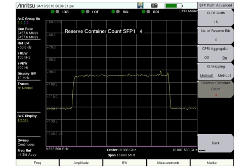
Reserve Containers
Most radio manufacturers start the IQ samples at the beginning of the CPRI stream. Some LTE carriers, however, may employ a frame structure where a number of containers at the start of the CPRI data flow are reserved, thereby offsetting the location of the first AxC group (AxC0). In this case, set a Reserve Container Count to shift the start location of the IQ data block. Refer to Custom Settings Menu. For example, a Reserve Container Count of 4 will offset the location of container group AxC0 to container number 4, skipping the reserve containers 0 through 3. See Figure: Reserve Container Count.
Reserve Container Count
IQ Bit Width
This is the IQ bit width, or sample width, for the digitized uplink and downlink signals. The parameter value is determined by the Radio Equipment Manufacturers. Selectable values are 10, 12, 15, and 16.
Reserve Bits
The reserve (or stuffing) bits are vendor-specific and are used with IQ bit width to align sample frequencies to the CPRI frame. Reserve bits can be set at 0 through 10. For LTE, 0 and 6 are the most common reserve bit values.
CPRI Aggregation
Aggregation is common with some LTE equipment manufacturers. It refers to the aggregation of smaller carriers to make one large carrier within one AxC. For example, two 5 MHz carriers can be aggregated to make a single 10 MHz carrier.
Note
If you know the equipment manufacturer, such as Nokia/ALu (Alcatel-Lucent), Ericsson, Huawei, or Samsung, you may select the appropriate radio preset and let the application auto-detect the line rate, the carrier bandwidth, and any available antenna carrier (AxC) groups. Refer to CPRI Parameter Automatic Detection.
To select CPRI parameter settings without the aid of a radio preset, refer to the CPRI Config Menu.
IQ Bit Mapping
Your Anritsu test instrument supports two IQ mapping methods. Method 1 is intended for dense packing of IQ data. Mapping method 3 is backward compatible with early releases of the CPRI specification.