To access the functions under the Limit menu, press the Shiftkey, then the Limit(6) key.
Limit lines can be used for visual reference only, or for pass/fail criteria using the limit alarm. Limit alarm failures are reported whenever a signal crosses a limit line.
Limit line can consist of a single segment or as many as 40 segments across the entire frequency span of the instrument. These limit segments are retained regardless of the current frequency span of the instrument, allowing the configuring of specific limit envelopes at various frequencies of interest without having to re-configure them each time the frequency is changed. To clear the current limit setup configuration and return to a single limit segment starting at the current start frequency and ending at the current stop frequency, press the Clear Limit submenu key.
The Limit On/Off submenu key turns the currently limit line on or off.
The Multi-Segment Edit submenu key displays a submenu that allows the creation or editing of single or multi-segment limit lines. The currently active limit point is marked by a red circle on the display.
The Limit Alarm submenu key enables the alarm to beep when a data point exceeds the limit.
The Clear Limit submenu key deletes all limit points for the currently active limit line and defaults to a single limit with an amplitude value selected to make it visible on the screen.
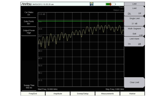
1. Press Shift and then Limit (6) to display the Limit menu.
2. Press the Limit On/Off key to turn on the Limit.
3. Press Single Limit and then use the arrow keys, rotary knob, or numeric keypad to change the limit value. Press Enter to complete.
4. Press the Limit Alarm key to turn on or off the Limit Alarm.
Segmented Limit Line
1. Press Shift and then Limit (6) to enter the Limit menu.
2. Press the Limit On/Off key to turn on the Limit.
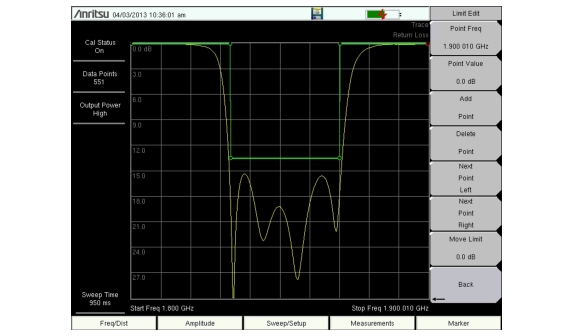
3. Press the Multi-Segment Edit key. The default limit line has two points. Add points as needed. The limit line example shown in Figure: Segmented Limit Lines has 3 segments requiring 6 points.
4. The selected point is highlighted in red. Once selected, a point can be moved left or right using the Point Freq (Distance for DTF measurements) key and up or down using the Point Value key.
Adjusting the Volume of Limit Alarm
1. Press Shift and then System (8)
2. Press the System Options submenu key.
3. Press the Volume key.
4. Use the Up/Down arrow keys or rotary knob to adjust the volume. Press Enter to complete.
Single Limit Lines
Segmented Limit Lines
Markers
Pressing the Marker function hard key below the display will bring up the Marker menu.
Press the Marker submenu key to select a marker. The underlined number indicates the active marker. The On/Off submenu key turns the selected marker On or Off. Use the arrow keys, the keypad or the rotary knob to move the marker. The current value for the selected marker is shown above the upper left corner of the graph.
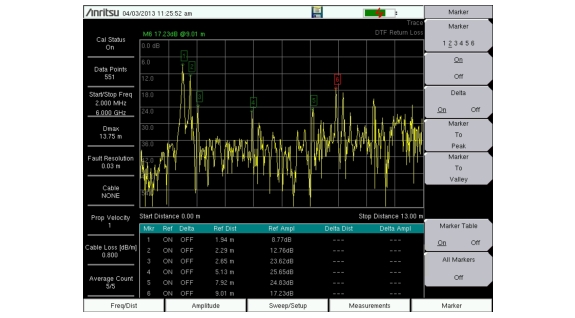
The Delta submenu key is available for each marker giving a total of 6 Delta markers. The Marker Table submenu key displays a table of up to six Markers and 6 Delta Markers simultaneously, showing frequency and amplitude respectively (Figure: Marker Table).
The Marker to Peak submenu key moves the currently selected marker to the peak of the trace. The Marker to Valley submenu key moves the currently selected marker to the valley of the trace.
Markers can be stored in the setups and recalled with the setup file at a later time.
Marker Table
Select, Activate, and Place a Marker / Delta Marker
Markers can be applied to active or recalled measurements. The instrument supports six reference and six delta markers.
1. Press the Marker main menu key.
2. Press the Marker 1 2 3 4 5 6 key to select Marker number 1. The underlined number indicates the active marker.
3. Use the arrow keys, the keypad, or the rotary knob to move the marker. The current value for the selected marker is shown above the upper-left corner of the graph.
4. The Delta Markers are available for each of the six reference markers. For the selected marker, Toggle Delta so that On is underlined to activate the Delta marker.
Marker To Peak and Marker To Valley
All the cable & antenna measurements include Marker To Peak and Marker To Valley selections that sets the peak and valley markers automatically.
1. Press the Marker main menu key.
2. Toggle the On/Off key to activate a marker.
3. Press Marker To Peak to set the marker to the peak of the measurement.
4. Press Marker To Valley to set the marker to valley of the measurement.
Peak Between M1 and M2 and Valley Between M1 and M2
When Marker 5 is selected, pressing the Marker Options key will bring up two more options.
1. Press the Marker main menu key.
2. Select Marker 5.
3. Press Marker Options and select Peak between M1 & M2 or Valley Between M1&M2.
Peak Between M3 and M4 and Valley Between M3 and M4
When Marker 6 is selected, pressing the Marker Options key will bring up two more options.
1. Press the Marker main menu key.
2. Select Marker 6.
3. Press Marker Options and select Peak Between M3 & M4 or Valley Between M3 & M4.
Marker Table
The Marker Table allows for viewing of up to six reference markers and six delta markers.