There are two power levels available for 2-port measurements: High (approximately –7 dBm) and Low (approximately –40 dBm). The low power setting should be used when making direct gain measurements of amplifiers. This will ensure that the amplifier is operating in the linear region. The High power setting is ideal when characterizing passive devices but can also be used when making relative gain or antenna-to-antenna isolation measurements in the field.
The Variable Bias Tee Option (Option 10) can be used to place between +12 V to +32 V, in 0.1 V increments, on the center conductor of the RF In port. It is designed to deliver 500 mA at +12 V and 250 mA at +24 V.
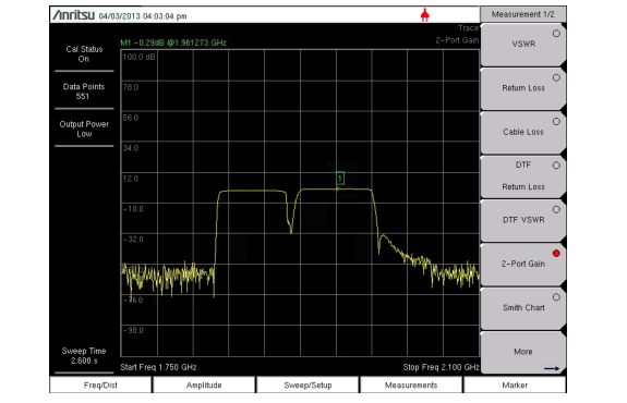
Example
This example describes a Gain measurement of a TMA (Tower Mounted Amplifier) using the built-in bias tee (Option 10).
Procedure
1. Press the Measurement main menu key and press 2-port Gain.
2. Press the Freq/Dist main menu key and set the Start Frequency and Stop Frequency.
3. Connect test port extension cables to the RF Out port and the RF In port.
4. Press the Shiftkey, then the Calibrate(2) key.
5. Press the Cal Type submenu key to set the calibration to 2-Port.
6. Press the Cal Power submenu key and set power to Low.
7. Press the Start Cal submenu key and perform a 2-port OSL calibration at the end of the extension cables. See 2-Port Calibration Procedure (OSLIT).
8. Connect the RF Out cable to the ANT port of the TMA.
9. Connect the RF In cable to RX port of the TMA.
10. Open the Bias Tee menu by pressing the following keys: Shift, System (8), the Application Options submenu key, and then the Bias Tee submenu key.
11. Set the appropriate voltage and current range for the amplifier using the Bias Tee Voltage and Current submenu keys. Note that the voltage will be applied to the center conductor of the RF In port.
12. Turn on the Bias Tee by pressing the Bias Tee On/Off submenu key.