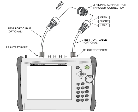
1. If a test port extension cable is to be used, connect the cable to the RF Out and/or RF In connector on the BTS Master. The calibration components will be connected at the end of the cable (Figure: 2-Port Calibration).
2. Set the frequency range, refer to Frequency for additional information.
3. Press the Shiftkey and then the Calibrate(2) key.
4. If none of the connectors shown in the DUT Connector Selector list are suitable for the application, there are two selections, User 1 and User 2, that can be custom defined. To edit the characteristics, select the User 1 or User 2 submenu key. The menu allows editing the offset lengths for the Open and Short, and the capacitance values for the Open. To change a value, press the appropriate submenu key, enter the desired value using the numeric keypad, and press Enter to accept. When all values are correct, press the Back submenu key to return to the Calibration menu.
2-Port Calibration
5. Press the Output Power submenu key to set the power level to Low (–40 dBm) or High (–7 dBm).
6. Press the Start Cal submenu key.
7. Connect the Open to the RF Out port (or to the end of the test port extension cable) and press the Enter key.
8. When prompted, connect the short to the RF Out port (or to the end of the test port extension cable) and press the Enter key.
9. When prompted, connect the Loads to the RF Out port (or to the end of the test port extension cable) and to the RF In port (or to the end of the test port extension cable) and press the Enter key.
10. Connect the RF Out port to the RF In port, including any test port extension cables used in the prior steps, and press the Enter key.
11. Verify that calibration has been performed properly by checking that the Cal Status On message is now displayed at the top of the status window.