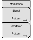
 | Signal Pattern Interferer Pattern |
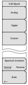 | Analog Digital Custom Spectrum Inversion Back |
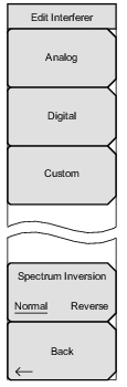 | Analog Digital Custom Spectrum Inversion Back |
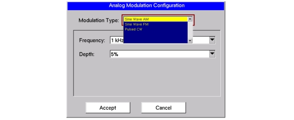 |
400 Hz |
1 kHz |
3 kHz |
5 kHz |
10 kHz |
15 kHz |
20 kHz |
5 % |
10 % |
20 % |
30 % |
50 % |
70 % |
90 % |
1 kHz |
5 kHz |
10 kHz |
50 kHz |
100 kHz |
500 kHz |
100 Hz |
500 Hz |
1 kHz |
5 kHz |
10 kHz |
50 kHz |
100 kHz |
500 kHz |
0.1 msec (10 kHz) |
1 msec (1 kHz) |
2.5 msec (400 Hz) |
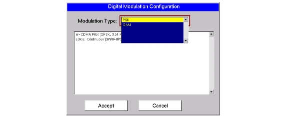 |
Modulation Type | Signal Pattern |
PSK | W-CDMA Pilot (QPSK, 3.84 Msym/s, RRC, alpha=0.22, PN9) EDGE Continuous (3Pi/8-8PSK, 270.833 ksym/sec, Lin-Gauss, PN9) |
QAM | DECT 16 QAM Continuous (1.152 Msym/s, RRC, alpha=0.5, PN9) J.83C Digital Cable (16 QAM, 5 Msym/s, RRC, alpha=0.13, PN9) DVB-C (16 QAM, 6.84 Msym/s, RRC, alpha=0.15, PN9) DECT 64 QAM (1.152 Msym/s, RRC, alph=0.5, PN9) US Digital 64 QAM (5.056941 Msym/s, RRC, alpha=0.18, PN9) |