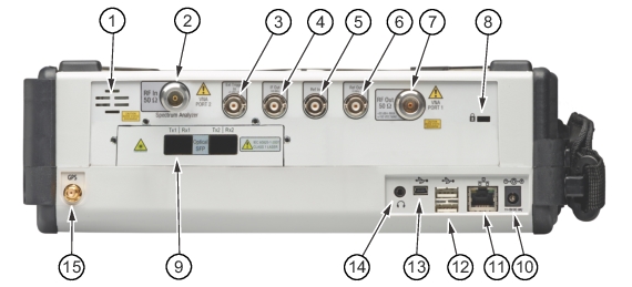
This is a 50 Ω Type‑N female connector. The maximum input is +30 dBm at ±50 VDC.
To prevent damage to your instrument, do not use pliers or a plain wrench to tighten the Type‑N connector. Do not overtighten the connector. The recommended torque is 12 lbf·in to 15 lbf·in (1.36 N·m to 1.70 N·m).
Ext Trigger In
A TTL signal that is applied to the External Trigger 50 Ω female BNC input connector causes a single sweep to occur. In the Spectrum Analyzer mode, it is used in zero span, and can be used to cause triggering to occur on the selected edge of the signal, either rising or falling. After the sweep is complete, the resultant trace is displayed until the next trigger signal arrives. To prevent damage to your instrument, do not use pliers or a wrench to tighten the BNC connector. Do not overtighten the connector.
IF Out 140 MHz (Option 89)
This 50 Ω BNC connector is for Zero Span 140 MHz IF Output with Option 89. To prevent damage to your instrument, do not use pliers or a wrench to tighten the BNC connector. Do not overtighten the connector.
Ext Ref In
The External Reference In port is a 50 Ω BNC female connector that provides for input of an external frequency reference. Refer to your Technical Data Sheet for valid frequencies. To prevent damage to your instrument, do not use pliers or a wrench to tighten the BNC connector. Do not overtighten the connector.
Ref Out 10 MHz
The External Reference Out port is a 50 Ω BNC female connector that provides 10 MHz at 0 dBm to –7 dBm. To prevent damage to your instrument, do not use pliers or a wrench to tighten the BNC connector. Do not overtighten the connector.
RF Out / VNA PORT 1
This is a 50 Ω Type N female connector. The maximum input is +23 dBm at ±50 VDC.
To prevent damage to your instrument, do not use pliers or a plain wrench to tighten the Type‑N connector. Do not overtighten the connector. The recommended torque is 12 lbf·in to 15 lbf·in (1.36 N·m to 1.70 N·m).
Optical SFP (Option 759)
The optical transceiver port is used to connect the instrument to the fiber optic CPRI or OBSAI link between a Radio Frequency Module (RFM) and a Base Band Module (BBM). The two SFP ports are present only when Option 759 (RF over Fiber hardware) is installed. Refer to the BTS Master Technical Data Sheet for transceiver part numbers and specifications.
Note
Option 759 requires either Option 752 (CPRI LTE RF Measurements) or Option 753 (OBSAI LTE RF Measurements). The combination of Option 759 and Option 752 is functionally identical to obsolete Option 751.
External Power
This is a 2.1 mm by 5.5 mm barrel connector, 12 to 15 VDC, < 5.0 A. The external power connector is used to power the unit and for battery charging. A green flashing indicator light near the power switch shows that the instrument battery is being charged by the external charging unit. The indicator is steadily illuminated when the battery is fully charged.
Warning
When using the AC Adapter, always use a three‑wire power cable that is connected to a three‑wire power outlet. If power is supplied without proper grounding, the user is at risk of receiving a severe or fatal electric shock.
LAN Connection
The RJ48C connector is used to connect the BTS Master to a local area network (LAN). Integrated into this connector are two LEDs. The amber LED shows the presence of a 10 Mbit/s LAN connection when On, and a 100 Mbit/s LAN connection when Off. The green LED flashes to show that LAN traffic is present. For additional information about the LAN connection, Ethernet connection, and DHCP, refer to LAN and DHCP.
USB Interface – Type A
The BTS Master can also be a USB Host and allow power sensors and USB memory devices to be connected to the instrument for storing measurements, setups, and files.
USB Interface – Type Mini‑B
The 5‑pin mini‑B USB 2.0 interface can be used to connect the MT8220T BTS Master directly to a PC. The first time the MT8220T is connected to a PC, the normal USB device detection by the computer operating system will take place. The CD‑ROM that shipped with the instrument contains a driver for Windows XP that is installed when Master Software Tools is installed. Drivers are not available for earlier versions of the Windows operating system. During the driver installation process, place the CD‑ROM in the computer drive and specify that the installation wizard should search the CD‑ROM for the driver.
Note
For proper detection, Master Software Tools should be installed on the PC prior to connecting the BTS Master to the USB port.
Headset Jack
The 3‑wire headset jack provides audio output from the built‑in AM/FM/SSB demodulator and from other sounds generated by the instrument. The jack accepts a 3.5 mm 3‑wire miniature phone plug such as those commonly used with cellular telephones.
GPS Antenna Connector
The GPS antenna connection on the BTS Master is type SMA(F). Selectable +3 VDC or +5 VDC antenna power. To prevent damage to your instrument, do not use pliers or a plain wrench to tighten the SMA connector. Do not overtighten the connector. The recommended torque is 8 lbf·in (0.9 N·m or 90 N·cm).
The MT8220T BTS Master includes a passive GPS antenna (2000-1733-R) which can be connected for acquiring GPS location data.