System performance issues are seen in two ways: excessive reflections (more common) caused by impedance mismatches, or excessive insertion losses (less common) caused by energy dissipated in the connectors or cables.
The two measurements that are used to determine communication system performance are:
• Return Loss or Standing Wave Ratio (SWR) for reflections.
• Cable Loss (Insertion Loss) for insertion losses.
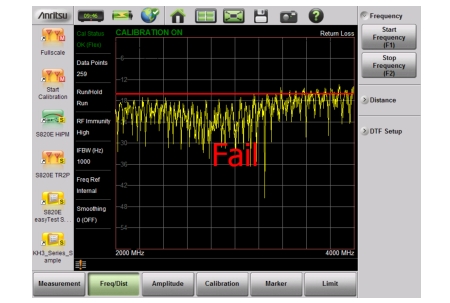
Remember that Return Loss and VSWR are typically Pass/Fail tests. They both measure reflection, but they display the results in different ways. For either measurement, set a limit line to the specification determined by the carrier and make the measurement. If the ENTIRE swept frequency range is below the limit line, then the test passes. If ANY part of the sweep is at or above the limit line, then the test fails.
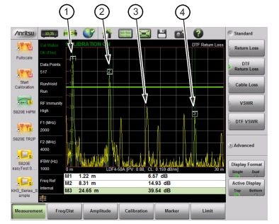
Distance to Fault Measurement Shows Failing Components
1.
Failure at Jumper (1.22 m)
2.
Possible Failure at 8.31 m
3.
Example of Good Connector (~30 dB)
4.
Precision Load Connected at End of Cable (24.65 m)
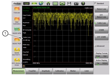
The second common Line Sweeping measurement is Cable Loss (Figure: Cable Loss Measurement). This is a measure of signal output power compared to input power. If output power is smaller than input power, then the loss comes from heat and leakage. Cable manufacturers will specify the loss per foot or meter at different frequencies and may call it attenuation. The Site Master has loss specifications preinstalled for many cable types.
The Cable Loss measurement is typically a Pass/Fail measurement. It requires a short or open at the cable end. This is a typical measurement specified on new installations or main transmission line replacement, but it is not typically tested on existing systems.
Note
Cable Loss cannot be measured with an antenna connected.