Four basic vector voltmeter measurement types are available: Reflection, Transmission, A/B (Port 1/Port 2), and B/A (Port 2/Port 1).
With Option 441 in the S820E, you can measure relative magnitude and phase of a DUT either directly (using the built-in source and couplers) or as a ratio function (A/B or B/A) using appropriate external accessories such as a CW signal source and either a power splitter or a coupler. Direct measurements can be 1-port (reflection) or 2-port (transmission) and may also be vector error corrected, thereby providing absolute measured values versus relative measured values. Option 441 is a stand‑alone option in the S820E and does not require the VNA Mode (Option 440) to provide full A/B and B/A ratio capability. All measurements made with Option 441 are based on CW signals. They are not swept frequency measurements.
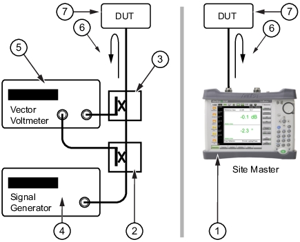
Reflection measurement (1‑port)
This technique is most often used for cable trimming, but it can also be used to validate the proper electrical length of any low loss DUT. It is most often used with a reference measurement (golden DUT) which is stored into memory, then subsequent DUTs may be measured and compared against the stored reference. As an option, the measurement port may be vector error corrected (via the calibration process, refer to Calibration, CAA) to provide optimal results. This is the simplest and most convenient VVM measurement. Best results are obtained when the DUT loss is < 20 dB. For a very lossy DUT, use the Transmission Measurement type.
Figure: Vector Voltmeter Reflection Measurement shows a block diagram comparison of the test configuration for the traditional Vector Voltmeter instrument method (left) and the equivalent measurement capability integrated within the Site Master in VVM mode (right) when the S820E is used for a reflection measurement.
Vector Voltmeter Reflection Measurement
(Left) Vector Voltmeter and (Right) S820E Site Master Equivalent Measurement
1
S820E Site Master
2
Coupler or Splitter
3
Coupler or Bridge
4
Signal Generator
5
Vector Voltmeter
6
Reflection Measurement
7
DUT (Device Under Test)
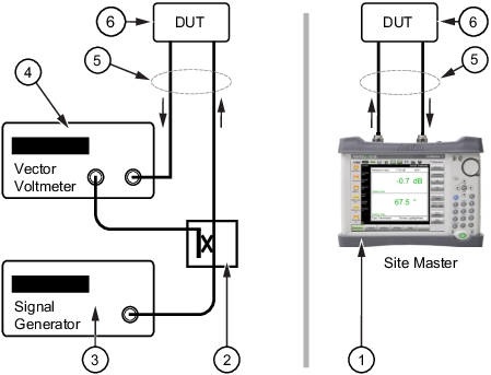
Transmission measurement (2‑port)
This technique uses the VVM function in a straightforward manner with its 2‑port setup. The transmission response of the DUT is measured from port 1 to port 2. The DUT amplitude and phase shift are measured by the highly sensitive port 2 receiver. The high dynamic range of this measurement is ideal when the DUT loss is high.
Figure: Vector Voltmeter Transmission Measurement shows a block diagram comparison of the test configuration for the Vector Voltmeter instrument method (left) and the equivalent measurement capability integrated within the Site Master in VVM mode (right) when the S820E is used for a transmission measurement.
Vector Voltmeter Transmission Measurement
(Left) Vector Voltmeter and (Right) S820E Site Master Equivalent Measurement
1
S820E Site Master
2
Coupler or Splitter
3
Signal Generator
4
Vector Voltmeter
5
Transmission Measurement
6
DUT (Device Under Test)
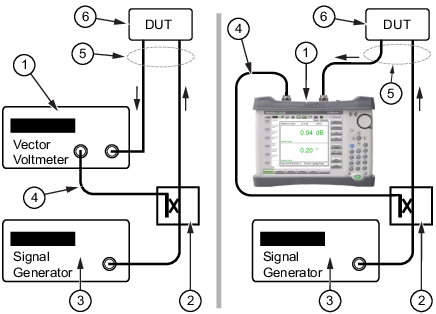
A/B or B/A Measurements
For Reflection or Transmission measurements, the S820E VVM function can replace the entire setup of source, VVM, and couplers, as shown in Figure: Vector Voltmeter Reflection Measurement and Figure: Vector Voltmeter Transmission Measurement. If the measurement setup still requires the use of an external source and couplers, however, then the S820E VVM function can replace only the original Vector Voltmeter by using the A/B or B/A measurement selection. The B/A setup is shown in Figure: Vector Voltmeter B/A Measurement with the traditional Vector Voltmeter instrument method (left) and the equivalent measurement using the Site Master in VVM mode (right). For these measurements, the reference signal is received on one port of the S820E (Port 1 for B/A and Port 2 for A/B) while the signal transmitted through or reflected from the DUT is received on the other port.
B/A Measurement
Vector Voltmeter B/A Measurement
(Left) Vector Voltmeter and (Right) S820E Site Master Equivalent Measurement