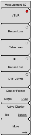
 | VSWR Press the VSWR submenu key to view the match in VSWR. Return Loss Return Loss is used to characterize RF components and systems. The Return Loss indicates how well the system is matched by taking the ratio of the reflected signal to the incident signal, and measuring the reflected power in dB. Cable Loss The cable loss test verifies the signal attenuation level of the cable. DTF Return Loss The DTF measurement displays return loss (or VSWR) values versus distance. If the frequency measurements fail or indicate a problem in the system, then the DTF measurement can be used to identify and pinpoint the exact location of the problem. The DTF measurement shows the return loss value of all the individual components including connector pairs and cable components. DTF VSWR The DTF measurement displays return loss (or VSWR) values versus distance. If the frequency measurements fail or indicate a problem in the system, then the DTF measurement can be used to identify and pinpoint the exact location of the problem. The DTF measurement shows the return loss value of all the individual components including connector pairs and cable components. Display Format: Select between having a single measurement or dual measurement display. Active Display Selects the active display, by displaying a red outline. More Opens the additional Measurement 2/2 menu shown in Figure: Measurement Menu (2 of 2). |