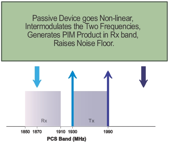
PIM is a form of intermodulation distortion that occurs in passive components normally thought of as linear, such as filters, combiners, surge protectors, cables, connectors, and antennas. When subject to the high RF powers found in cellular systems, however, these devices can generate spurious signals.
Passive Intermodulation (PIM) shows up as a set of unwanted signals created by the mixing of two or more strong RF signals in a non‑linear device, such as from a loose or corroded connector, or in nearby rust. Other names for PIM include the “diode effect” and the “rusty bolt effect”.
Many symptoms that could be indicators of PIM problems include the following:
• Receiver desensitization (raised noise floor)
• Rx Diversity alarms
• Spectral regrowth in the transmitter mask
• Excessive dropped or blocked calls, or both
• Reduced data rates
• Cell site coverage shrinking
• Complaints of interference from neighboring cell site owners
PIM signals in the cell receive band can raise the receive noise floor, increase the bit error rate, and shrink the reception area for cellular communications. PIM can come from junctions; from improperly tightened, damaged, or corroded connectors; from filters, combiners, and surge protectors; and from damaged antennas. Other sources include rusty components, such as mounts and bolts or nearby metal structures.
Power in dBm and dBc
A measurement reading in dBm is absolute power. A measurement value with units of dBc is relative power.
For example, if you set TX1 and TX2 to 43 dBm and get a measurement result of –120 dBm (the measurement result as absolute power), this represents a relative power of –163 dBc. The calculation is as follows:
–120 dBm – 43 dBm = –163 dBc
[measured power in dBm] minus [transmitted power in dBm]
equals [relative power in dBc]
The term relative power, in this example, is referring to the original output power setting of 43 dBm. When stated in units of dBc, the received PIM power is relative to (is being compared to) the transmitted power level of one test tone. The difference between the transmitted power (in dBm) and the measured PIM power (in dBm) is the relative power, which is then expressed in units of dBc.
Note
The use of dBc units is not applicable to Noise Floor measurements, because the transmitters are not On during this measurement.
Why Test for PIM?
Anritsu has developed the PIM Master to verify and troubleshoot Passive Intermodulation (PIM). The PIM Master generates two high‑power tones, usually in the transmit band of interest. It displays and measures the third‑order, fifth‑order, or seventh‑order intermodulation products returning from the DUT to the PIM Master. (The third, fifth, and seventh‑order intermodulation products can be measured only if they fall into the range of the receive band.) Using Distance‑to‑PIM technology, the PIM Master can identify the location of PIM sources both inside the antenna system and beyond.
PIM testing provides a measurement of the overall linearity of the antenna system and the surrounding environment. A formula for determining third-order intermodulation (IM3) frequencies is provided in section Intermodulation Distortion.
When more carriers are added to a site and transmit power is increased, the impact of PIM on site performance becomes more severe. A low‑traffic site might not exhibit the same performance problems as a busy site.
Line Sweeping and PIM Testing
Line Sweep testing and PIM testing are very different tests. Both are important and are accurate measures of the ability of the cell site to provide service and to perform optimally.
PIM testing measurements indicate the overall linearity of an antenna feed line, the antenna, and the area illuminated by the transmitted signal. The Line Sweep measurements indicate the overall impedance matching of all of the components in an antenna feed line. Both tests need to be performed in order to ensure the overall quality of a site.
PIM testing requires both low system loss and good return loss (VSWR) to achieve an accurate measurement. If PIM testing is performed prior to line sweep testing, then you may not be aware of the impedance characteristics of the transmission line. High insertion loss attenuates the PIM test signals, which prevents full test power from reaching the specific components that require stringent PIM testing. Poor return loss reflects a percentage of the PIM test signals back into the test set, which causes some signal cancellation that can report a false pass. In other words, poor line sweep performance can lead to a false pass for a PIM test.
By performing the line sweep test prior to PIM testing, you can be confident the insertion loss and return loss data are at acceptable levels. This data in turn ensures that the PIM test signals actually reach all components at the correct signal level, offering the most accurate indicator of true PIM performance. By constructing a system using modern, low-PIM practices, the need to break the transmission system back open will be minimized. If the lines are disassembled again to repair or clean a connector, the line sweep and PIM testing will need to be repeated.
Causes of PIM
PIM is caused by two or more strong RF signals mixing in a non‑linear device. These non‑linear devices, or junctions, occur in improperly tightened, damaged, or corroded connectors or in damaged antennas. Rusty components, such as mounts and bolts, are also suspect when hunting for sources of PIM.
PIM can be generated anywhere in the RF path. The RF path includes not only the antenna feed system but also the antenna itself, as well as objects illuminated by the antenna. Because RF currents are strongest inside the coaxial cables and physically close to the antenna radiating aperture, non‑linear junctions or materials in these locations are more likely to generate harmful PIM than non‑linearities away from these regions.
The following list provides guidelines for preventing PIM at cellular installations:
• Visually inspect RF connectors and RF cables before assembly to remove all metal flakes.
• Verify that RF mating surfaces are clean and free of mechanical damage prior to assembly.
• Wipe mating surfaces with a lint‑free wipe, moistened with alcohol to remove dirt and oils.
• Face coaxial cables downward while cutting so that any metal flakes that are produced fall out rather than into the coaxial cable.
• Always use sharp cutting tools when preparing the ends of coaxial cables.
• Use the correct cable preparation tools for the type and size coaxial cable with which you are working.
• Remove any metal burrs from the cut edges of coaxial cables prior to connector attachment.
• Prevent foam dielectric material from getting trapped between metal contacting surfaces.
• Remove all adhesive residue from the mating region of the coaxial cable center conductor.
• Properly align RF connectors prior to assembly in order to prevent damage to mating surfaces.
• Apply the torque that is specified by the manufacturer to all mated pairs of RF connectors.
• Do not over‑torque RF connectors because doing so may cause damage to contacting surfaces.
• Prevent excessive vibration and shock to RF components when transporting them to the site.
• Prevent RF components from impacting the tower while hoisting.
• Leave protective caps on RF connectors until you are ready to attach the mating cable.
• Avoid loose metal objects within the half‑power beam widths of base station antennas, cable trays, vent pipes, air conditioning units, metal flashing, guy wires, and so forth.
PIM Testing Example
PCS Band PIM Testing
Intermodulation Distortion
The intermodulation distortion (IMx) is a mathematical function of F1 and F2.
3rd Order Intermodulation (IM3) = 2F1 – F2 or (IM3) = 2F2 – F1
2nd Order Intermodulation (IM2) = F1 + F2 or (IM2) = F1 - F2