1. Connect the DUT to the test port of the PIM Master.
2. Press the Measurements main menu key to display the Measurements menu.
3. Press the Test submenu key so that On is underlined and the Test submenu key is outlined in Red. Testing begins.
4. Save the current measurement by pressing the Save Measurement submenu key. The Save Measurement dialog box opens.
5. Type a name for the measurement to be saved and press Enter.
DTP Measurement Example
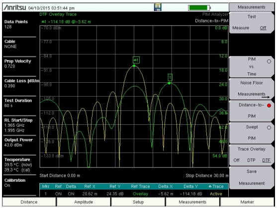
As shown in Figure: DTP Measurement Example, the Distance‑to‑PIM trace (yellow trace with peak near 15 m) and Distance‑to‑Fault trace (green trace with peak near 21 m) are both automatically measured and presented when a DTP measurement is made. Distance‑to‑Fault (DTF) acts like a map to identify RF connector locations in the system. In this example, the two traces indicate that the PIM problem is located at the first connector past the input.
Up to six markers can be placed at points of interest on the DTF and DTP traces, and the marker table will display the signal parameters at each marker point. After each measurement, Marker 1 is always placed at the peak value of the DTF measurement, and Delta Marker 1 is always placed at the peak of the DTP measurement.