Trace Overlay is a feature allowing comparison in the field between a Distance‑to‑PIM trace that is active and a Distance‑to‑PIM or Distance‑to‑Fault trace that is saved in memory (an overlay trace). This is useful for determining (at a site) the distance between an unknown PIM source and a known PIM source or reflection.
DTP/DTP Overlay
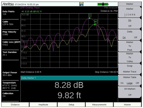
To determine if a PIM source is beyond the antenna or inside the feed system, you need to know exactly where the antenna radiating surface is located. This can be determined by placing a bag of steel wool on an antenna radome and performing a Distance‑to‑PIM measurement. The resulting peak in the measurement marks the location of the antenna radiating surface. Place this trace into memory (overlay trace), and then measure Distance‑to‑PIM again with the steel wool removed. This new active trace shows the distance to the actual PIM sources at the site. The distance between the peak of the active trace (site PIM) and the overlay trace (PIM marker) shows how far in front of the antenna the PIM source is located if the distance value is positive. If the distance value is negative, then the unknown PIM source is before the antenna, inside the feed system. Refer to Trace.
DTP/DTP Trace Overlay Example – PIM Source 10 Ft from End of Cable
DTP/DTF Overlay (Manual Method)
Comparing the PIM location to known reflections on the line is also useful for troubleshooting PIM locations. Before beginning PIM measurements, the cable system sweep tests should already have been performed. Often, operators require a system DTF measurement and a cable length measurement (DTF with a short circuit at the end of the cable) as part of the close‑out package. If these measurements were made using a PIM Master with Option 331, then these measurements are available in memory for future overlays.
Use the Trace function to select the desired DTF trace (refer to Trace). Using the Trace Overlay submenu key, select DTF. The selected DTF trace appears on the screen along with the active Distance‑to‑PIM trace (site PIM). A delta marker is automatically generated and shows the relative distance between the DTF peak and the DTP peak.
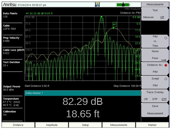
The example in Figure: DTP/DTF Trace Overlay Example – PIM Source Beyond End of Cable shows an active Distance‑to‑PIM measurement (site PIM) with a Cable Length DTF trace. The DTF trace accurately identifies the end of the cable. In this case, the PIM source is 18.65 ft beyond the end of the cable, indicating that the site PIM is likely beyond the antenna.
DTP/DTF Trace Overlay Example – PIM Source Beyond End of Cable
DTP/DTF Overlay (Automatic Method)
In cases where high resolution DTF traces are not available to import, low resolution DTF traces can be generated through the PIM test port. By default, Distance-to-PIM measurements have this low resolution DTF measurement turned on. If not desired, then the automatic DTF overlay can be turned off in the Setup menu.
DTF measurements made through the PIM test port have limited swept frequency range due to filters inside the PIM analyzer. Each PIM analyzer has a different internal filter, resulting in different swept frequency ranges for each model number. As a result, the DTF resolution is different for each PIM Master model. For short measurement distances, an imported DTF measurement may be preferred in order to distinguish closely spaced connections. For longer measurement distances, the automatic DTF overlay is usually sufficient.
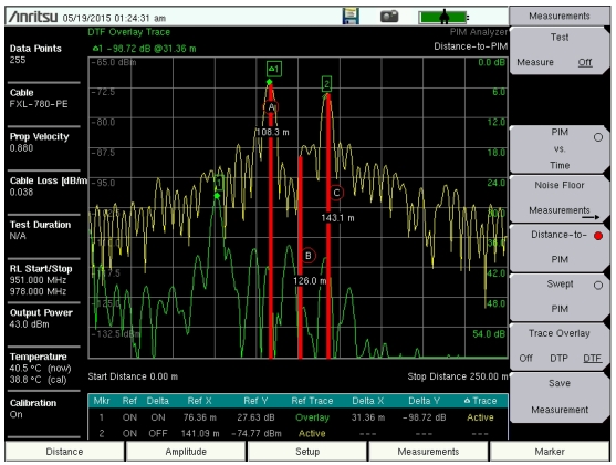
Figure: DTP/DTF Trace Overlay Example shows an example of an automatic DTP/DTF overlay made at 900 MHz in a distributed antenna system (DAS), where the length of the system was more than 140 m. As can be seen, the DTF resolution in this case is sufficient to identify splitters and antenna locations along the DAS branch. The PIM locations can be compared to these known reflections to help isolate PIM faults in the sector. The red bars seen here are the DTP enhanced resolution feature described in Enhanced Resolution.
DTP/DTF Trace Overlay Example
Overlay Using Line Sweep Tools Software
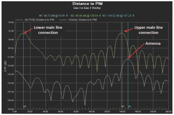
After you leave the site, Anritsu Line Sweep Tools (LST) also provides a method to overlay multiple DTP results. Figure: Distance‑to‑PIM Overlay of Sector Main and Diversity Paths shows an overlay of two DTP measurements from the main receive path and the diversity receive path of a sector. One line has very good PIM performance, but the other line needs repair. Using the good line (lower trace) as a reference, you can clearly see that the PIM problems on the bad line are 11 feet away from the radio at the main line connection and 9 feet behind the antenna at the top (also at a main line connection). LST also could be used to report site improvements by creating an overlay of saved measurements that are taken before and after repairs.
Distance‑to‑PIM Overlay of Sector Main and Diversity Paths