During calibration, RF power is present, and the red RF On light is illuminated.
Calibrations are temperature‑dependent. A temperature deviation of approximately 20 degrees Celsius voids an existing calibration. Two temperatures are displayed in a white font (in all PIM measurement modes) in the Instrument Settings Summary, just above the Calibration On/Off message. One is the temperature in the PIM Master now, and the other is the temperature in the PIM Master at calibration.
When the current temperature (labeled now) changes ±8 °C of the calibration limit, the font color of the current temperature is displayed in yellow. This color changes to red if the current temperature exceeds the calibration limit ±10 °C from the calibration limit. N/A is displayed for the calibration temperature when no valid calibration file exists for the current instrument settings.
All calibrations are valid for an initial 12‑hour limit. If the PIM Master remains On, and if all settings remain consistent, then the current calibration file remains effective. If any setting is changed after 12 hours, including a power cycle of the PIM Master (Off and On), then a warning is presented indicating that the current calibration is more than 12 hours old. The message instructs the user to verify the instrument residual PIM level and re-calibrate if necessary. Calibrations can be used again after settings are changed and then returned to the previous settings for which the calibration was performed.
The standard calibration calibrates Distance-to-PIM, Swept PIM, PIM vs. TIME, and Noise Floor - Time View for the current instrument settings. A user-defined calibration dialog is available allowing users to select specific calibrations they wish to perform, and this allows multiple power-level calibrations to be performed at the same time (refer to the Passive Intermodulation Analyzer Measurement Guide that is listed in Other Documents for more information).
If you are performing a Noise Floor Spectrum View measurement, a separate calibration is required. Press the Start Cal Spectrum View button in the Noise Floor menu, and then follow the on‑screen instructions to calibrate the Spectrum View (alternately, you can use the “User Defined Calibration Dialog Box” as described previously).
These steps describe the standard calibration process:
1. Press Shift then Cal (2) to open the Calibration menu.
2. In the Calibration menu, press the Start Calibration submenu key.
3. If conducting a high-band intermodulation measurement (i.e., PCS, 1900 MHz, or IM2), ensure that the PIM Master receiver port is open (disconnected) and skip to Step 4. For all other bands, connect the appropriate PIM standard onto the test port of the PIM Master or at the end of the PIM test cable.
4. Connect an appropriate Low PIM Load onto the PIM Master output port or to the Low PIM standard if used.
5. Press Enter to calibrate or Esc to exit.
6. If you are conducting a high-band intermodulation measurement as noted in Step 4, skip to Step 13. During the calibration, CALIBRATION IN PROCESS... is displayed on the measurement screen in red letters, and a beep is emitted when this step is completed.
7. When prompted, remove the PIM standard and the Low PIM Load, and then connect only the Low PIM Load.
8. Press Enter to calibrate or Esc to exit.
9. If the Low PIM Load is better than –88 dBm, then the calibration continues, as in Step 10.
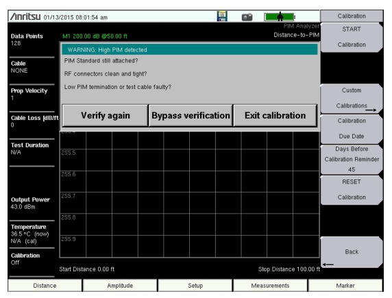
If the Low PIM Load just installed has high PIM, then this calibration will not be useful. If the measured PIM is worse than –88 dBm, then a warning is displayed. See Figure: Bad Load Detection Warning. The displayed warning provides 3 options.
a. Verify again After you have made corrections, press this button to continue the calibration.
b. Bypass verification Press this button to ignore the warning and continue the calibration.
c. Exit calibration Press this button to abort the current calibration.
10. During the calibration, CALIBRATION IN PROCESS... is displayed on the measurement screen in red letters, and a beep is emitted when this step is completed.
11. When prompted, remove all components from the test port leaving nothing connected at the point of calibration (Open circuit).
12. Press Enter to calibrate or Esc to exit.
13. During the calibration, CALIBRATION IN PROCESS... is displayed on the measurement screen in red letters. When calibration is complete, two beeps are emitted, and Calibration On is displayed at the bottom of the Instrument Settings Summary.
Bad Load Detection Feature
The second step of a calibration requires removal of the PIM Standard and reattachment of the Low PIM Load. If the Low PIM Load has measured PIM worse than –88 dBm, then the WARNING: High PIM detected dialog box is displayed (as shown in Figure: Bad Load Detection Warning).