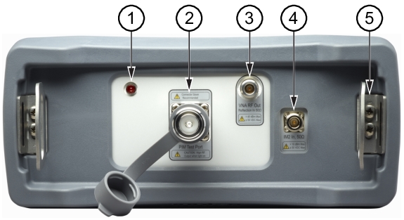
Type 7/16 DIN(f), 50 Ω test port connector that is used to perform PIM versus Time, Swept PIM, Noise Floor, and Distance‑to‑PIM (DTP) measurements.
To prevent damage to your instrument, do not use pliers or a plain wrench to tighten the DIN connector. Do not over-tighten the connector. The recommended torque is 25 N · m (~18 lbf · ft). To prevent rotation, secure the PIM test connector or the recommended connector saver with a wrench when attaching a test lead.
VNA RF Out Connector, Type‑N, female, 50 ohms (Option 331). This test port is available only on instruments with Site Master Option 331. It is used to perform Return Loss, VSWR, Cable Loss, and Distance‑to‑Fault (DTF) measurements. Hand tighten this connection. Do not use a wrench.
IM2 In Connector, Type‑N, female, 50 ohms (Option 902). This test port is available only with frequency Option 902. It is used to receive second order intermodulation products. Hand tighten this connection. Do not use a wrench.
The Strap Brackets hold the Handle Strap and can accommodate a Carabiner. Note that each bracket is secured to the PIM Master with 2 screws. The handle is sewn to the brackets, but is not shown in the figure in order to reveal the bracket design. See Figure: Instrument Enclosed in the Soft Carrying Case for the complete bracket, mounted and in use.