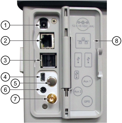
This 2.1 mm by 5.5 mm barrel connector is used to power the unit and for battery charging. Input is 12 VDC to 15 VDC at up to 5.0 A.
Warning
When using the AC‑DC Adapter, always use a three‑wire power cable that is connected to a three‑wire power line outlet. If power is supplied without grounding the equipment in this manner, then the user is at risk of receiving a severe or fatal electric shock.
The RJ45 connector is used to connect the PIM Master to a local area network. Integrated into this connector are two LEDs. The amber LED shows the presence of a 10 Mbit/s LAN connection when on, and a 100 Mbit/s LAN connection when off. The green LED flashes to show that LAN traffic is present. For additional information about the LAN connection, Ethernet connection, and DHCP, refer to LAN and DHCP.
This interface has two connectors for flash drive and USB Power Sensor. The MW82119B PIM Master can also be a USB Host and allow various USB Flash Memory devices to be connected to the instrument for storing measurements, setups, files, and firmware upgrades. Either USB connection can be used with a USB power sensor (but only one power sensor at a time).
The USB 2.0 interface can be used to connect the MW82119B PIM Master directly to a PC for data transfer. The first time the PIM Master is connected to a PC, the normal USB device detection by the computer operating system will take place. Drivers are available for Windows XP (or later).
Note
For proper detection, Line Sweep Tools should be installed on the PC prior to connecting the PIM Master to the USB port.
The GPS antenna connection on the PIM Master is type SMA(F). Selectable +3 VDC or +5 VDC antenna power.
To prevent damage to your instrument, do not use pliers or a plain wrench to tighten the SMA connector. Do not overtighten the connector. The recommended torque is 8 lbf · in (0.9 N · m or 90 N · cm).