The TRAC:IQ:DATA? query returns a modified version of the SCPI standard (IEEE 488.2) block data format. The header contains three fields with a newline delimiter separating the header from the I/Q binary data:
#AXL\n
A is a single ASCII digit specifying the number of digits in X.
X is one or more ASCII digits specifying the number of bytes of binary I/Q data and ASCII GPS location coordinates.
L is the ASCII string containing the GPS location in the form 'latitude, longitude' in decimal degrees. The coordinates record where the I/Q capture was triggered.
\nis a single byte newline delimiter marking the end of the GPS location component and start of the I/Q data. The I/Q data is in binary format and is described below.
I/Q Capture Block Mode
This mode captures a single block of IQ data. I/Q data is first stored to high speed DDR2 SDRAM buffer memory and then it can be saved to flash memory or sent to a remote user via Ethernet. The capture length (duration) is limited by the size of the buffer memory (256 Mbytes) and I/Q data rate, which is determined by the capture bandwidth.
The IQ capture bandwidth must be set to one of the available values listed in the table below. For each selectable bandwidth, the output data rate for a single I/Q data pair is listed in Table: IQ Capture Bandwidth Values. The output data rate does not change, regardless of bit resolution.
IQ Capture Bandwidth Values
I/Q Bandwidth
Output Data Rate MSPS
IQ Sample Pairs/Sec
20 MHz
76.25 / 3
25416666.67
13.3 MHz
76.25 / 4
19062500
6.67 MHz
76.25 / 8
9531250
2.67 MHz
76.25 / 20
3812500
1.33 MHz
76.25 / 40
1906250
667 kHz
76.25 / 80
953125
267 kHz
76.25 / 200
381250
133 kHz
76.25 / 400
190625
66.7 kHz
76.25 / 800
95312.5
26.7 kHz
76.25 / 2000
38125
13.3 kHz
76.25 / 4000
19062.5
6.67 kHz
76.25 / 8000
9531.5
2.76 kHz
76.25 / 20000
3812.5
1.33 kHz
76.25 / 40000
1906.3
The maximum capture length is limited by memory, capture bandwidth and bit resolution. Table: Maximum I/Q Block Capture Length shows the maximum capture length.
1 For 20 MHz capture bandwidth, when IQ bit resolution is set to 32 bits, the lower 8 bits are zeros. Therefore the maximum effective bit resolution is 24 bits for 20 MHz bandwidth.
I/Q Frame Structure
I/Q data is organized into two levels: frame and extended frame. The lowest level is a 64 bit frame. which may contain one to four I/Q sample pairs depending on the selected I/Q bit resolution. The second level is an extended frame which can be used for the stamp information. The first column of the IQ vector contains Q and the second column contains I.
The 64 bit frame contains one to four I/Q sample pairs depending on the selected I/Q bit resolution.
I/Q Bit Resolution
IQ Sample Pairs per 64 Bit Frame
24
1
16
2
10
3
8
4
24 Bit Resolution
16 Bit Resolution
10 Bit Resolution
8 Bit Resolution
Note
The frame structure will be modified slightly when there is a time stamp. This will be described in a later section.
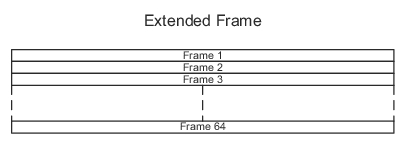
I/Q Extended Frame
An extended frame consists of 64 frames. When time stamp information is used, each frame contains one bit of a 64 bit time stamp data. An extended frame is 64 frames that contain a time stamp.