 | |
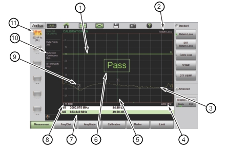
1 | Limit line (green for Pass, red for Fail) |
2 | Measurement type |
3 | Active trace (Yellow) |
4 | Stop frequency (F2) |
5 | Marker 1 (Marker to Peak) |
6 | Pass message (active trace is entirely below the upper limit line in Return Loss measurement) |
7 | Marker table |
8 | Start frequency |
9 | Marker 2 (Marker to Valley) |
10 | Measurement details (also Menu Shortcuts) |
11 | User-defined setup and menu shortcuts (not available in Classic mode) |