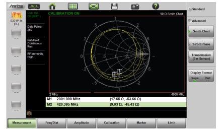
The Smith Chart is a graphical tool for plotting impedance data versus frequency. It converts the measured reflection coefficient data into impedance data and displays it in a manner that makes the Smith Chart a useful tool for determining and tuning input match. Markers can be used to read the real and imaginary parts of the complex impedance. See the example in Figure: Smith Chart Measurement. This impedance plot reveals which matching elements (capacitance, inductance) are necessary to match a device under test to the reference impedance, which can be set to either 50 ohms or 75 ohms. See Figure: Set Reference Impedance for Smith Chart Calculations and refer to Amplitude Menu.
Smith Chart Measurement
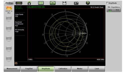
Set Reference Impedance for Smith Chart Calculations
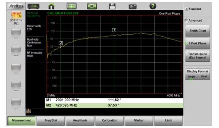
1-Port Phase
The S331P can display the phase of the reflection measurements at the RF port. The Phase display range is from –450 degrees to +450 degrees.
The 1-port phase measurement is most useful when making relative measurements (comparing the phase of one device to the phase of another) by utilizing the Trace Math function (Trace – Memory).
1-Port Phase Measurement
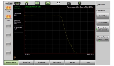
Transmission (Ext. Sensor)
To make more accurate cable loss measurements, especially for cables with more than 10 dB of loss, you can use the Transmission measurement with External Sensor. For this measurement, connect the cable under test to the RF port of the S331P and connect a USB power sensor to the other end of the cable. USB extenders can be used for long cable runs. This measurement gives accurate results of cable loss up to 30 dB. This is a scalar measurement, providing only magnitude data (no phase) and, therefore, does not use vector error correction for its calibration steps. Instead, it uses a sensor reference calibration. Figure: External Sensor Transmission Measurement is a cable loss measurement example with an external sensor transmission.
External Sensor Transmission Measurement
For best results when performing both transmission and return loss measurements on the same cable, the return loss should be measured with a good-quality termination at the end of the cable.
Note
For a list of external USB sensors that are supported by the S331P for transmission measurements, see the S331P Technical Data Sheet.