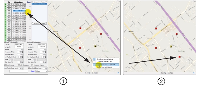
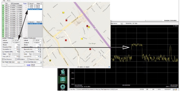
Figure: Add a Monitor shows a basic simulator screen that consists of three monitors and one interferer. The monitors are shown in red and the interferer is shown in yellow.
1. On the map, right-click a desired monitor location. A context menu is displayed.
2. Click Copy Coordinates to Clipboard.
3. In the GPS Coordinates column, slide the mouse over a latitude and as shown. This will perform the copy coordinate function.
Note that the coordinates for monitor ports 5 through 24 are positioned beyond the zoomed-in map and will not display.
Add a Monitor
1. Copy Monitor D Coordinates
2. Added Monitor D
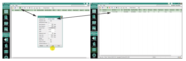
Monitor a Signal
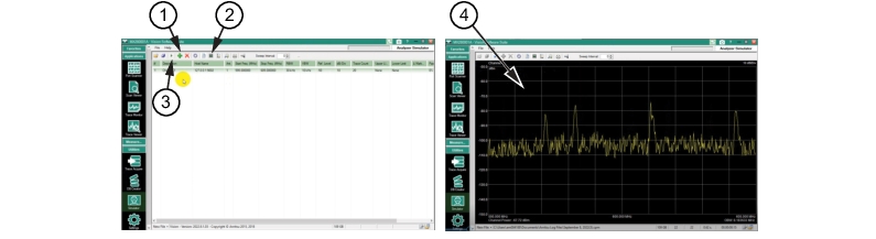
Each monitor on the screen will produce a simulated measured signal. To display a signal to monitor, open the Port Scanner program from the Applications menu and add a signal as shown in Figure: Show Signal to Monitor.
1. Open the Port Scanner program from the Applications menu.
2. Click the Add button on the Port Scanner task bar to display the Add Channel dialog.
3. Type the port from the Simulator program that will display the signal. In the example below, type 127.0.0.1:9002.
4. Click the Add button at the bottom of the “Add Channels” dialog to show the Hostname with its signal parameters. This will add port 9002 and it’s parameters to the display.
4. Displayed Simulator Signal on the Port Scanner Display
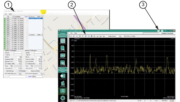
Pop-out Active Windows
Use the pop-out button to view the signal and navigate the Simulator control; at the same time. Press the pop-out button shown in Figure: Pop-out Window. The two windows can be viewed simultaneously.
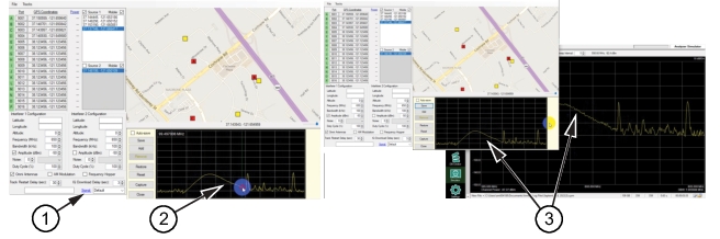
The screen below shows four red monitors: Port A, Port B, Port C, and Port D. The interferers are added by double-clicking a position on the map. Shown below, the active interferer is yellow with a black square in the middle. The Coordinates for this interferer are displayed in the Interferer 1 Configuration window and also in the Source 1 Window. The frequency is typed in as 601 MHz so it shows within the Port Scanner bandwidth display. Changing other Interferer 1 Configuration parameters will also be displayed on the Port Scanner window.
View Simulator Interferer Signal
Draw a Signal
Use the Signal editing window to manually create a signal to display as shown in Figure: Draw Signal.
1. Press the Signal button on the Simulator Program.
2. Click-hold to draw a signal as desired across the Simulator signal display to create a signal that will also display on the Port Scanner program display.
3. Continue to draw as much as desired and then press Save to create the signal in the Port Scanner display. Or check autosave will save each drawn signal.