Menu | Description |
File | Open Database Opens the database folder that has been set from “Set Database Root Folder”. Exit Exit the File menu. |
Map | Load Map Load a customer selected map to the screen. Existing Maps Load a map from an existing map folder. |
Help | Help See Help Menu. |
Menu | Description |
Run Button Press once to operate the cross-polarization measurement continuously. Press again to stop. | |
Run Once Press to run cross polarization measurement once. Press again to run the measurement once again. | |
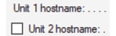 | Hostname Enter a Unit 1 hostname. A multiport RSM requires only 1 hostname. If using two RSMs, check the “2 hostname” box and type the hostname of the second RSM. If using two RSMs, both will be using a Port 1. |
 | Start/Stop Frequency Type or use the increment/decrement keys to enter the start and stop frequency in MHz. Range is 7 kHz to 6 GHz. |
 | RBW/VBW Press the arrow key to set the RBW and VBW. |
Reference Level Set the reference level for the cross polarization measurement. Range is –80 dB to 20 dB. | |
Preamp Check to turn on the preamp. |
Menu | Description |
Run Button Press to run cross polarization measurement continuously. Press again to stop. | |
Run Once Press to run cross polarization measurement once. The measurement will run one time. Press again to run the measurement once again. | |
Hostname Type or press the pull-down arrow to enter a unit 1 hostname. A multiport RSM requires only 1 hostname. If using two RSMs, check the “2 hostname” box and type the hostname of the second RSM. If using two RSMs, both will be using a Port 1. | |
 | Marker (n) Check the box to display the marker 1 through 4 on the trace data display. See Marker Measurement Display. |
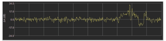
Graph Mode Set the time graph display to show either the difference or ratio of the channel power between the two signals as a function of time. Difference: Set time graph to Difference mode. Ratio: Set time graph to Ratio mode. 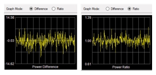 |
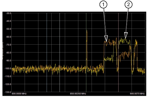 |
1. Trace One - Burnt Orange Color 2. Trace Two - Yellow Color |
 |
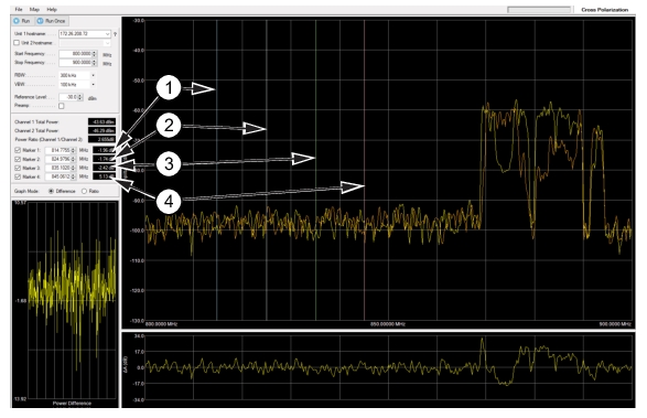 | |
1. Marker 1 Readout with Blue Colored Marker Displayed 2. Marker 2 Readout with White Colored Marker Displayed 3. Marker 3 Readout with Green Colored Marker Displayed 4. Marker 4 Readout with Red Colored Marker Displayed |