 | |
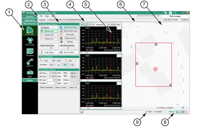
1. PoA Finder Menu Button 2. PoA Toolbar 5. Monitor Display Area | 6. Locator Map 9. GPS Coordinates |
| |
1. PoA Finder Menu Button 2. PoA Toolbar 5. Monitor Display Area | 6. Locator Map 9. GPS Coordinates |
Menu | Description |
File | Open Database Opens the database folder that has been set from “Set Database Root Folder”. Set Database Root Folder Opens the database folder set the “Set Database Root Folder”. Recent Databases Click to display the most recent databases used. Exit Exit the File menu. |
Map | Load Map Load a customer selected map to the screen. Existing Maps Load a map from an existing map folder. |
Help | Help See Help Menu. |
Icon | Description |
Spectrum Monitor Spectrum monitors selected on the Base Station and Channel Directory to locate the interfering signal. The short lines that extend out from the square depict the direction of the antenna used. For a view of the interfering signal’s bearing using a single monitor, click the desired monitor represented by a number or star then click 1Monitor from the Monitor pull-down list above the top trace display. | |
Base Station Base Stations that are close by that can be used to locate the interfering signal. Click on this base station icon to make it one of the three base stations locating the interfering signal. At the same time, the last active number icon base station will turn into a star icon. The trace for the base station will change accordingly in the trace panel. | |
Interfering Signal The approximate location of the interfering signal based on the information from the selected base stations. |
Icon | Description |
Capture Live Traces From Remote Monitors Initially when the Source Locator opens, the last sweep taken is displayed in the trace panels for each of the selected monitors. Click Live to view the trace measurements in real-time. Click again will stop the sweep of the displays. | |
Show Traces from Database This allows you to scroll through both live and database data while looking at location estimates. Live traces in the Locator window do not get stored to the database. This icon button changes state to indicate the active selection: Live Data: The two cylinder icon shows that the trace graphs are pulling from the database. Stored Data: The TV icon shows the three trace graphs displayed are from live data. | |
Toggle Toggle the display between database view and live capture view | |
Hide/Show Hide/Show locate options and settings | |
Frequency Field Type a marker frequency. Capture Live Traces From Remote Monitors must be selected to stop the sweeping, then type a Frequency entry. The display marker will move to selected location. Click Capture Live Traces From Remote Monitors to restart the sweep. |