 |
Note | Select AUTO REF LEVEL to help ensure that harmonics and spurs are not introduced into the measurements. |
 |
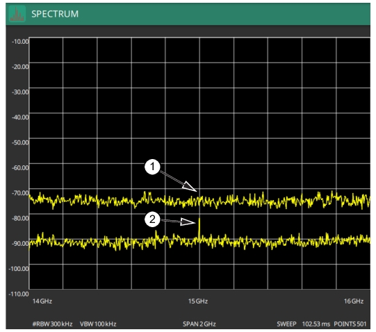
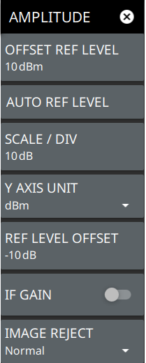
 | OFFSET REF LEVEL The reference level is the top graticule line on the measurement display. If the reference level offset is not zero, the offset reference level is displayed at this location. Pressing the plus (+) or minus (–) control increments the value by 10. The plus/minus (+/-) button on the keypad toggles between positive and negative values. AUTO REF LEVEL Auto reference level automatically adjusts the reference level to place the highest signal amplitude at about two graticule lines from the top based on the position of the trace at the time the button is pressed. SCALE/DIV The scale can be set from 1 dB per division to 15 dB per division. The default setting is 10 dB. Pressing the plus (+) or minus (–) control increments the value by 1. Y AXIS UNIT Displays the y-axis amplitude units in dBm. REF LEVEL OFFSET Reference level offset compensates for the presence of external input attenuation or gain. The offset is applied to all amplitude related parameters and to measurements such as the y-axis scale and marker measurements. The default offset value is 0 dB. Pressing the plus (+) or minus (–) control increments the value by 10. The plus/minus (+/-) button on the keypad toggles between positive and negative values. Refer to Reference Level Offset for External Loss or External Gain. IF GAIN Turns the IF gain On or Off. Default is Off. The analyzer has an IF amplifier with approximately 20 dB of gain. When you can turn on the IF Gain without overloading the analyzer (reference levels of –10 dBm or less), it allows full use of the dynamic range of the analyzer. If the reference level is changed to be more than –10 dBm and IF gain was on, it will be turned off for any reference level over –10 dBm. Likewise, the IF gain cannot be turned on for a reference level over –10 dBm. IMAGE REJECT The MS276XA employs special image rejection algorithms to reduce or eliminate spurs and images in the receiver. Under normal operation, the analyzer will take two IF samples (a high side and a low side) and compare the two to reduce or eliminate unwanted spurs or images. This setting selects an image reject algorithm of Normal, High Only, or Low Only. Normal is the combination of both the high-side and the low-side IF samples, which provide the benefit of spur/image rejection. The High Only and Low Only settings offer no image rejection and only show the results from the single IF sample obtained (either high or low). High Only or Low Only settings results in faster overall sweep speed, but with no spur or image reduction at all. In Zero Span, the Low Only setting is automatically selected unless IMAGE REJECT is set to High Only. |