To select 5GNR summary measurement go to main menu and press MEASURE > MEASUREMENT >5GNR Summary. The 5GNR summary measurements are set up using the SETUP Menu (5GNR Summary). The 5GNR summary measurements are used for compliance testing of 5GNR networks and can evaluate active antenna systems for beamforming profiles and dynamic physical layer attributes of the transmitted signal.
The instrument can analyze a single physical-layer cell or multiple physical-layer cells at one time. The following considerations apply to each measurement.
Single PCI:
• Better for conducted measurements, directional antenna measurements, or if only one cell is present.
• Only one cell is reported. If multiple cells are present, the analysis may jump to different cells based on which cell presents the highest RSRP value at each measurement cycle, or not analyze any of the cells.
Multi PCI:
• Better sync in over the air field conditions.
• Multiple Cells can be reported and sorted on various measurement parameters.
This section illustrates several 5GNR summary measurements using both single PCI and multi PCI analysis techniques.
5GNR Summary Single Beam View
5GNR summary measurements in single beam view provide the same information as the multi beam view with added measurements as described in Figure: 5GNR Summary – Single Beam View.
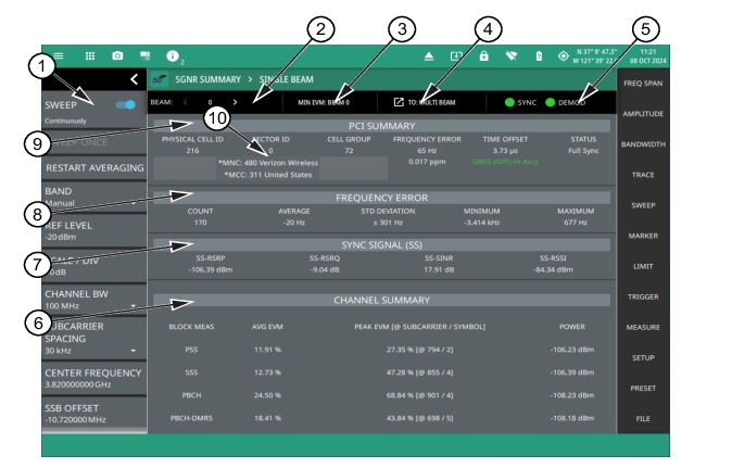
5GNR Summary – Single Beam View
1. 5GNR Analyzer Status Panel: Each measurement features a unique status panel that displays settings and information relevant to the current measurement and view settings. This panel provides quick access to the measurement frequency, subcarrier spacing, channel bandwidth, and band configuration. See Status Panel (5GNR Summary).
2. BEAM: This field indicates the current beam summary page. A maximum of 64 beams (numbered 0 to 63) can be individually displayed in single beam view. You can cycle through the beam pages using the left/right (</>) arrows or touch the number to select the desired beam.
3. MIN EVM BEAM: This field shows which beam measures lowest error vector magnitude (EVM).
4. SINGLE/MULTI BEAM: This field shows the current view setting. Touch this field to toggle between SINGLE BEAM or MULTI BEAM views. You can also change the view setting from the MEASURE menu.
5. SYNC/DEMOD: Valid 5GNR measurements require the signal synchronization and demodulation. The indicators here blink green when the received signal is synchronized and properly demodulated, indicating that you have a valid measurement.
6. Channel Summary: For the current beam, shows the average error vector magnitude (EVM), peak EVM (@ subcarrier/symbol) and received power in dBm for each block measurement:
• PSS: The primary synchronization signal provides the primary frame boundary (i.e., the position of the first symbol in the frame).
• SSS: Similar to PSS, the secondary synchronization signal provides the secondary sub-frame boundary.
• PBCH: This is the physical broadcast channel, the main purpose of which is to carry the broadcast information block.
• PBCH-DMRS: In 5GNR measurements, the PBCH decoding relies on a demodulation reference signal (DMRS, which is a physical layer reference signal used for decoding) rather than a cell specific reference signal (CRC).
7. Sync Signal (SS) Summary Data: Shows the following synchronization signal summary data for the current beam:
• SS-RSRP: Secondary synchronization signal reference signal received power measured in dBm.
• SS-RSRQ: Secondary synchronization signal reference signal received quality measured in dB.
• SS-SINR: Secondary synchronization signal-to-noise and interference ratio measured in dB.
• SS-RSSI: Secondary synchronization signal reference signal received indicator measured in dBm.
8. Frequency Error: This section shows the frequency error of all the measured signals. It is the difference between the measured carrier frequency and the specified carrier frequency. This measurement is only as accurate as the frequency reference that is used and is typically only useful with a good external frequency reference or GNSS (GPS). It consists of the following data:
• Count: The total number of frequency measurements included in the averaging measurement.
• Average: The average value of all frequency measurements made.
• Standard Deviation: The measure of the spread of frequency measurements. The standard deviation is the average difference of all measurements from the average frequency measurement. Typically 68% of all measurements will fall within the standard deviation value shown.
• Minimum: The single lowest frequency value measured.
• Maximum: The single highest frequency value measured.
9. PCI Summary: This section shows the physical cell ID summary data, including the sector ID, cell group number, frequency error, time offset, and sync status. Sync status can indicate if there is a PSS, SSS, or Beam Index failure, Full Sync, or an Unknown condition. Also noted is the instrument’s reference clock accuracy of Internal, External, or GNSS (GPS) high accuracy (requires GPS).
10. MNC/MCC Info: This area shows the Mobile Network Code (MNC) and Mobile Country Code (MCC) codes along with the carrier and the country name. Touch this info to open SIB MEASUREMENT dialog. Note that the asterisk symbol on this information indicates the presence of LAST SIB DECODE info as shown in Figure: 5GNR SIB MEASUREMENT and LAST SIB DECODE.
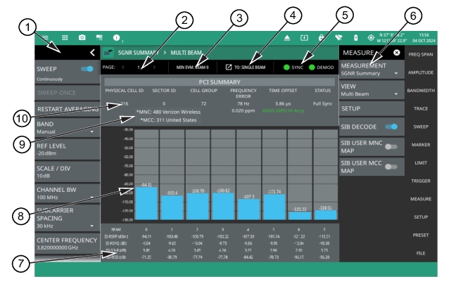
The following measurement is set up to display 5GNR summary data in a multiple beam view. In multi beam view, a maximum of eight beams can be displayed at once on a single page. The instrument can capture data for as many as 64 beams in a total of eight pages.
5GNR Summary – Multi Beam View
1. 5GNR Analyzer Status Panel: Each measurement features a unique status panel that displays settings and information relevant to the current measurement and view settings. This panel provides quick access to the measurement frequency, sub-carrier spacing, channel bandwidth, and band configuration. See Status Panel (5GNR Summary).
2. PAGE: This field indicates the current multi beam page. A maximum of eight pages (numbered 1 through 8) with eight beams (numbered 0 to 63) on each page can be displayed in multi beam view. You can cycle through the pages using the left/right (</>) arrows or touch the number to select the desired page.
3. MIN EVM BEAM: This field shows which beam measures the lowest error vector magnitude (EVM).
4. SINGLE/MULTI BEAM: This field shows the current view setting. Touch this field to toggle between SINGLE BEAM or MULTI BEAM views. You can also change the view setting from the MEASURE menu.
5. SYNC/DEMOD: Valid 5GNR measurements require the signal synchronization and demodulation. The indicators here blink green when the received signal is synchronized and properly demodulated, indicating that you have a valid measurement.
6. MEASURE MENU: Turn on SIB DECODE toggle to view the Mobile Network Code (MNC) and Mobile Country Code (MCC) code. Turn on SIB USER MNC/MCC MAP toggles to enable or disable custom user configuration of MCC, MNC pairs to mobile network names mapping.
7. Sync Signal Data: For each beam, the following synchronization signal summary data is displayed:
• SS-RSRP: Secondary synchronization signal reference signal received power is defined as the linear average over the power contributions of the resource elements that carry secondary synchronization signals measured in dBm).
• SS-RSRQ: Secondary synchronization signal reference signal received quality measured in dB.
• SS-SINR: Secondary synchronization signal-to-noise and interference ratio is defined as the linear average of the noise and interference power contribution over the resource elements carrying secondary synchronizing signals with the same frequency bandwidth.
• SS-RSSI: Secondary synchronization signal reference signal received indicator measured in dBm.
8. Beam Display: This area shows the received signal strength of each beam as a vertical bar. The top of the bar is annotated with the maximum signal strength (in dBm). The number of beams displayed depends on how many beams are defined by the band configuration. From 1 to 8 beams can be displayed at once on a page. When more than 8 beams are measured, additional beams can be accessed from additional pages. The beams are numbered from 0 up to 63. If you touch a beam, the view changes to display the selected beam in single beam view.
9. MNC/MCC Info: This area shows the MNC and MCC codes along with the carrier and the country name. Refer to SIB Measurement for detailed information.
10. PCI Summary: This area shows the physical cell ID summary data, including the sector ID, cell group number, frequency error, time offset (time offset value is the difference in time between the measured start of the 5G frame and the GPS 1 second clock pulse. If the time offset value is shown with an asterisk symbol then it means that either a Grand Master Clock (GMC) time offset or a time delay offset have been applied. The time offset value without an asterisk symbol signifies that no time offset corrections have been applied), and sync status. Also noted is the instrument’s reference clock accuracy of Internal, External, or GNSS (GPS) high accuracy (requires GPS).
Secondary synchronization signal reference signal received quality (SS-RSRQ) is defined as the ratio of N×SS-RSRP / NR carrier RSSI, where N is the number of resource blocks (RB) in the NR carrier RSSI measurement bandwidth. The measurements in the numerator and denominator shall be made over the same set of resource blocks.
RSSI definition in the standard:
New Radio (NR) carrier Received Signal Strength Indicator (NR carrier RSSI), comprises the linear average of the total received power (W) observed only in certain OFDM symbols of measurement time resource(s), in the measurement bandwidth, over N number of resource blocks from all sources, including co-channel serving and non-serving cells, adjacent channel interference, thermal noise etc.
Anritsu RSSI calculation:
Narrow band RSSI: Sum (Power of ith symbol of SSB in the SSB BW(total 240 REs)) / 4, i = 0,1,2,3
RSRQ calculation:
RSRQ = SS-RSRP/(Narrow band RSSI / 20), since the number of RBs in SSB is fixed at 20.
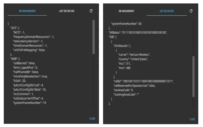
SIB Measurement
The MNC consists of either two or three decimal digits number used to uniquely identify a given network from within a specified country. Note that MNC of 001 is not the same as MNC of 01. Click on the MNC to view the SIB MEASUREMENT dialog that includes the System Information Block (SIB) and Master Block Information (MIB) data. Refer to “SIB Measurement” on page 2-34 for detailed information.
The MCC consists of three decimal digits excluding digits 1 and 8. The first digit of the mobile country code identifies the geographic region. Click on the MCC to view the SIB MEASUREMENT dialog that includes the System Information Block (SIB) and Master Block Information (MIB) data. Refer to 5GNR SIB/MIB Decode chapter for more information on the SIB measurement header sections tables and the corresponding fields, sub fields and their description.
In 5GNR MIBs and SIBs are used to carry different system information to customer premises equipment (CPE). The SIB messages are sent on PDSCH through RRC layer. SIB1 is carried under “SystemInformationBlockType 1” message name. Other SIBs (SIB2 to SIB11) are carried under “SystemInformation” message name and can contain multiple SIBs in the one message.
SIB1 is always sent in sub-frame #5 of the Radio-Frame, and continues retransmitting the same message in each 20 ms with different redundancy versions. Each 80ms a new SIB1 is transmitted.
The MIB message is broadcasted on PBCH. There is only one type of MIB. MIB is always sent in sub-frame #0 of the Radio-Frame, and continues retransmitting the same message in each 10 ms with different redundancy versions. Each 40ms a new MIB is transmitted.
Follow the steps below to view the SIB and MIB decodes:
• Press MEASURE menu and turn on SIB DECODE toggle. Notice the display of MNC and MCC information displayed in the PCI Summary section right below the PCI value.You can turn off the SIB DECODE toggle if the SIB decode is not necessary to make 5G Summary measurements.
• Touch the MNC and MCC info area on the instrument display to open SIB MEASUREMENT dialog. Notice that you can still view the SIB Measurement dialog by touching the MNC and MCC info area even without any code being displayed. See Figure: 5GNR Summary – Single Beam View.
• Scroll to the bottom of the SIB MEASUREMENT dialog to check the status message. If the status message is “statusSib1DecodeDone” then the instrument has successfully decoded MNC and MCC information.
• If the status message is “statusCoreset0Unavailable” it means that the SIB does not contain any MCC/MNC information to decode. This situation can legitimately occur if the cell site being tested is a supplementary link. In this case the mobile device would initially connect to a different band and the SIB1 information is provided by that band. For example, the 5G band could be from a non stand-alone network and the frequency band could be used to inform the mobile device of the MCC/MNC. Refer to Anritsu Hardware Status for descriptions on the status messages.
• Press CLOSE to close the SIB MEASUREMENT dialog on the instrument.
Note
The Anritsu Remote and Report Tools (ARRT) PC application provides a few additional capabilities in the SIB Measurement dialog, such as COPY MIB, COPY SIB and COPY ALL, to save data on your computer. On the other hand, saving a setup file saves the MIB and SIB measurement data onto your instrument.
5GNR SIB MEASUREMENT and LAST SIB DECODE
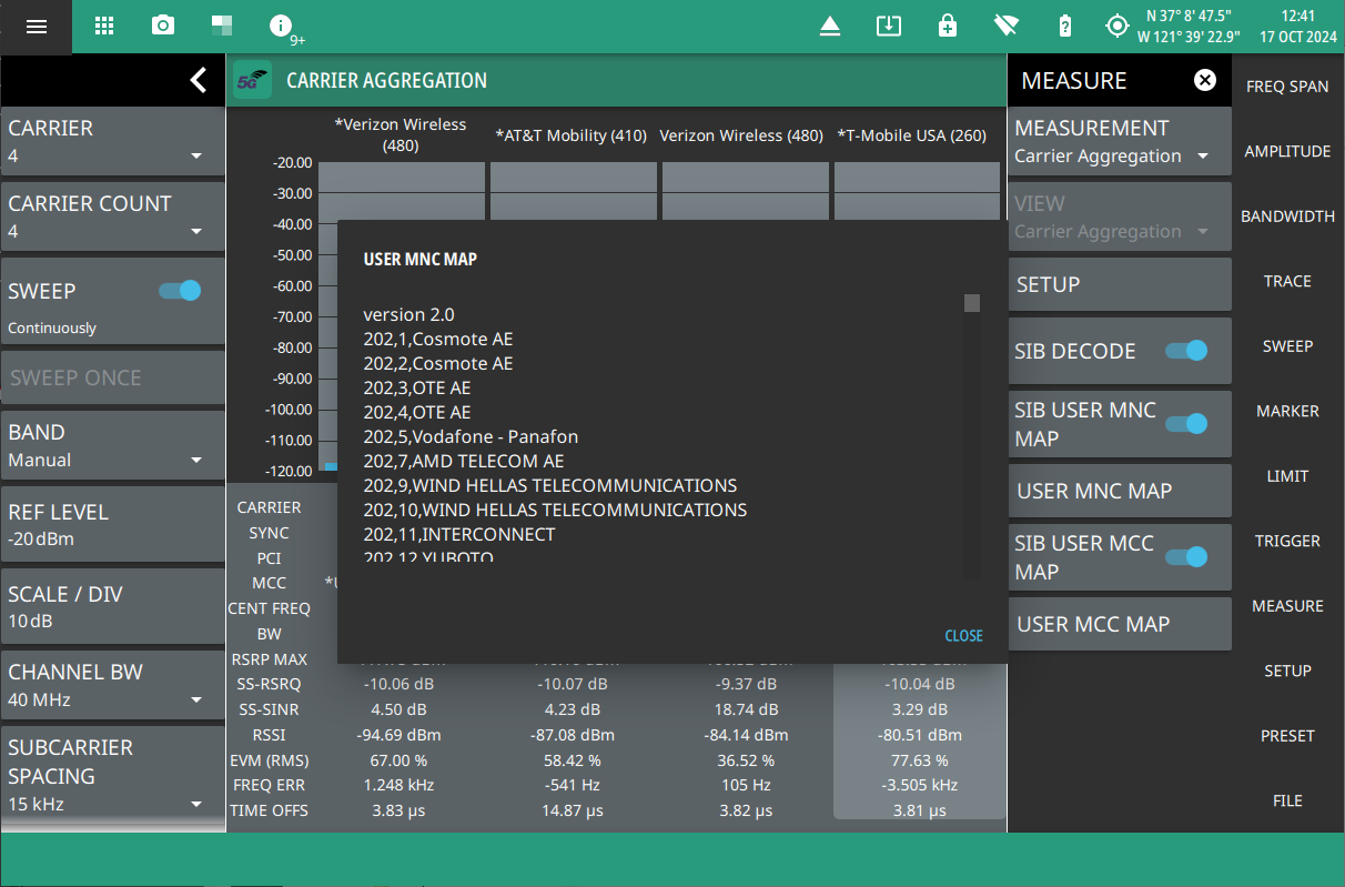
SIB USER MNC/MCC MAPS
The default MCC/MNC results displayed by the instrument use an ITU library. As new networks are licensed, or networks change ownership or branding, the library may become out of date. Users can create their own MCC/MNC map of network operator names to ensure the displayed results reflect the most recent friendly name for any given network.
Access SIB USER MNC/MCC MAP toggles from MEASURE menu.
Note that these toggles are only enabled when custom user configuration files are placed in the root directory (Internal) of the instrument’s memory, or onto an external memory such as an encrypted FIPS compliant USB memory device. The configuration files can be saved as either as.txt or .csv files.
When the user configuration files are not saved in the instrument a parse error message will be displayed in the notification bar and the map toggles cannot be turned on.
To view the USER MNC MAP dialog (see Figure: 5GNR USER MNC MAP) create a configuration file such as carriers.txt or carrier.csv and add the desired MNC, MCC codes and the corresponding carrier names and save the file either on a USB device or in the internal folder of your instrument.
The file contents must follow a specific format as explained below:
version <version code>
XXX,YYY,Carrier Name, wherein XXX represents the MNC and YYY represents the MCC.
For example,
version 1.0
260,1,T-Mobile / PTC S.A
Make sure to rename the version number for e.g. version 2.0 if new entries are added to the configuration files. This will allow you to invoke the recently updated configuration file.
5GNR USER MNC MAP
Similarly, to view USER MCC MAP dialog create a configuration file such as “countries.txt” and add the desired MCC codes and the corresponding country names with the format as explained below:
The file contents must follow a specific format as explained below:
version <version code>
YYY,Country Name, wherein YYY represents the MCC
For example,
version 1.0
311, United States
5GNR USER MCC MAP
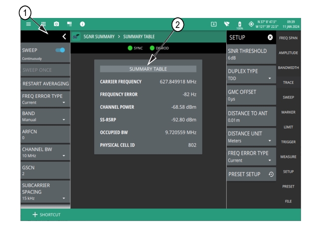
5GNR Summary Table View
The 5GNR summary table displays the measured values of carrier frequency which is calculated as the sum of center frequency and frequency error, channel power, SS-RSRP power, occupied bandwidth and PCI ID, as shown in Figure: 5GNR Summary Table View.
5GNR Summary Table View
1. 5GNR Analyzer Status Panel: Each measurement features a unique status panel that displays settings and information relevant to the current measurement and view settings. This panel provides quick access to the frequency error type, subcarrier spacing, channel bandwidth, and band configuration. See Status Panel (5GNR Summary).
2. SUMMARY TABLE: This field indicates the current beam summary page.
• Carrier Frequency: The sum of center frequency and frequency error.
• Frequency Error: Frequency error is the difference between the received center frequency and the specified center frequency. This is tied to external frequency reference accuracy and is typically useful only with a good external frequency reference. To view average frequency error, select AVERAGE from FREQ ERROR TYPE drop-down in the status panel/SETUP menu.
• Channel Power: The total power transmitted within a specified frequency or channel bandwidth.
• SS-RSRP: Secondary synchronization signal reference signal received power measured in dBm.
• Occupied BW: The bandwidth containing 99% of the total integrated power within the transmitted spectrum around the selected center frequency.
• Physical Cell ID: The physical-layer cell ID value.
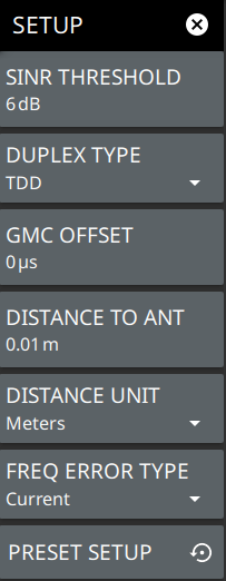
SETUP Menu (5GNR Summary)
The 5GNR Summary SETUP menu is available in MEASURE > MEASUREMENT > 5GNR Summary > SETUP.
5GNR SETUP Menu (5GNR Summary)
-
SINR THRESHOLD
Sets the threshold level that the secondary synchronization signal-to-noise and interference ratio that a beam must overcome to be analyzed.
DUPLEX TYPE
Selects either frequency division duplex (FDD) or time division duplex (TDD).
GMC OFFSET
Changes the time offset result to correct for the GMC (Grand Master Clock) offset at the gNB antenna when GPS 1 PPS correction is not applied at the gNB antenna plane. The time offset measurement is indicated with an asterisk symbol if the GMC offset is applied.
DISTANCE TO ANT
Sets the straight line distance between the gNB antenna and the instrument receive port when testing OTA. The range can be set from 0.01 m to 50,000 m (approximately 0.3 ft to 164,000 ft) with a resolution of 0.01 (m or ft). The distance to antenna feature is useful in removing the time delay between the amount of time the RF signal travels from the base station to instrument OTA. If the time delay is applied then the time offset measurement value will be indicated by an asterisk symbol.
DISTANCE UNIT
Sets the distance unit of measure to Meters or Feet.
FREQUENCY ERROR TYPE
Selects the frequency error type as either current or average. Shows the current frequency error value when CURRENT is selected. Shows the average of frequency error of all the measured channels. Note that this is only available in 5GNR summary table view.
PRESET SETUP
Presets the SETUP menu to default settings.
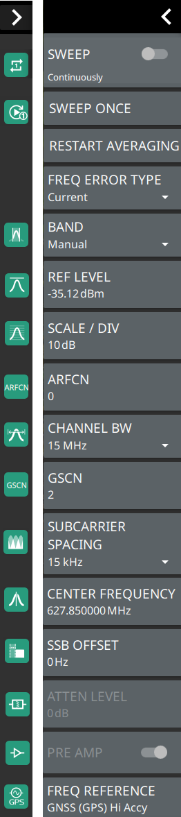
Status Panel (5GNR Summary)
The status panel illustrated in this section is unique to the current analyzer and to the particular measurement and view that is selected. Figure: Status Panel (5GNR Summary Measurement) shows the 5GNR status panel that covers the 5GNR Summary measurements (selected via MEASURE> MEASUREMENTS menu).
Status Panel (5GNR Summary Measurement)
SWEEP: Toggles the current sweep setting between continuously or sweep once.
SWEEP ONCE
When sweep is set to single sweep, SWEEP ONCE updates the measurement display. Data continues to be captured in the background.
RESTART AVERAGING
Restarts the average frequency error value of the all the frequency measurements made.
FREQUENCY ERROR TYPE
Selects the frequency error type as either current or average. Shows the current frequency error value when CURRENT is selected. Shows the average of frequency error of all the measured channels. Note that this is only available in 5GNR summary table view.
BAND
Select MANUAL, GLOBAL ALL or one of the predefined bands. Selecting MANUAL hides ARFCN and GSCN settings. Selecting a predefined band or GLOBAL ALL enables the ARFCN and GSCN settings.
REF LEVEL
The reference level is the top graticule line to the left on the measurement display.
SCALE/DIV
The scale can be set from 1 dB per division to 15 dB per division. The default setting is 10 dB. Selecting the plus (+) or minus (–) control changes the value by 1. SCALE/DIV is not available when linear y-axis amplitude units are selected.
ARFCN
ARFCN is the Absolute Radio Frequency Channel Number. The ARFCN is a unique identification number assigned to each radio channel within a communications spectrum. The ARFCN can be used to calculate the center frequency of the radio channel. The available input range is dependent on the selected band.
CHANNEL BW
Sets the measurement channel bandwidth. The available bandwidth settings depend on the selected band and bandwidth option installed in the instrument. Refer to “Options Settings” in Instrument Overview chapter of the user guide.
GSCN
GSCN is the Global Synchronization Raster Channel. The GSCN identifies the mapping of the synchronous signal block (SSB). The available input range is dependent on the selected band.
SUBCARRIER SPACING
Sets the subcarrier spacing. The available input range is dependent on the selected band.
CENTER FREQUENCY
When the band is set to MANUAL, sets the center frequency of the measurement channel. Changing the center frequency sets the band to MANUAL.
SSB OFFSET
SSB is the Synchronous Signal Block. The SSB Offset sets the frequency offset between the SSB and the overall resource block.
FREQ REFERENCE
Indicates the current frequency reference source of Internal, External, or GNSS (GPS) Hi Accuracy (requires GPS). The instrument automatically selects the frequency reference in the following order of priority: external, GPS, then the internal time base.
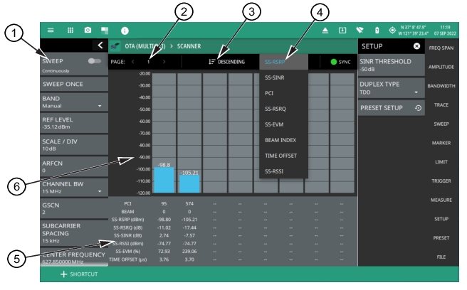
OTA (Multi PCI) Scanner View
To select OTA (Multi PCI) measurement go to main menu and press MEASURE > MEASUREMENT >5GNR OTA (Multi PCI). The OTA (Multi PCI) measurements are set up using the SETUP Menu (OTA (Multi PCI)). The following measurement is set up to display 5GNR summary data of multiple cells in a multiple beam scanner view. In scanner view, a maximum of eight beams can be displayed at once on a single page. The instrument can capture data for as many as 64 beams in a total of eight pages.
5GNR OTA (Multi PCI) – Multiple Beam Scanner View
1. 5GNR Analyzer Status Panel: Each measurement features a unique status panel that displays settings and information relevant to the current measurement and view settings. This panel provides quick access to the measurement frequency, subcarrier spacing, channel bandwidth, and band configuration. See Status Panel (5GNR OTA (Multi PCI)).
2. PAGE: This field indicates the current multi beam page. A maximum of eight pages (numbered 1 through 8) with eight beams (numbered 0 to 63) on each page can be displayed in multi beam view. You can cycle through the pages using the left/right (</>) arrows or touch the number to select the desired page.
3. Ascending/Descending Sort: This field selects the sort order of the selected value. The beam data is sorted from left to right in either ascending or descending order of magnitude.
4. SS-RSRP, SS-SINR, PCI, SS-RSRQ, SS-EVM, Beam Index, Time Offset, SS-RSSI: Selects on which value to sort.
5. PCI Summary Data: For each beam, the following synchronization signal summary data is displayed:
• PCI: Physical-layer cell identity.
• Beam: Beam index number.
• SS-RSRP: Secondary synchronization signal reference signal received power measured in dBm.
• SS-RSRQ: Secondary synchronization signal reference signal received quality measured in dB.
• SS-SINR: Secondary synchronization signal-to-noise and interference ratio measured in dB.
• SS-RSSI: Secondary synchronization signal reference signal received indicator measured in dBm.
• SS-EVM: Error vector magnitude measured in percentage.
• Time Offset: Time difference between the measured start of the 5GNR frame and the 10 ms frame trigger, which is automatically synchronized to GNSS (GPS) when the instrument has GNSS (GPS) lock.
6. Beam Display: This area shows the received signal strength of each beam as a vertical bar. The top of the bar is annotated with the maximum signal strength (in dBm). The number of beams displayed depends on how many beams are defined by the band configuration. From 1 to 8 beams can be displayed at once on a page. When more than 8 beams are measured, additional beams can be accessed from additional pages. The beams are numbered from 0 up to 63.
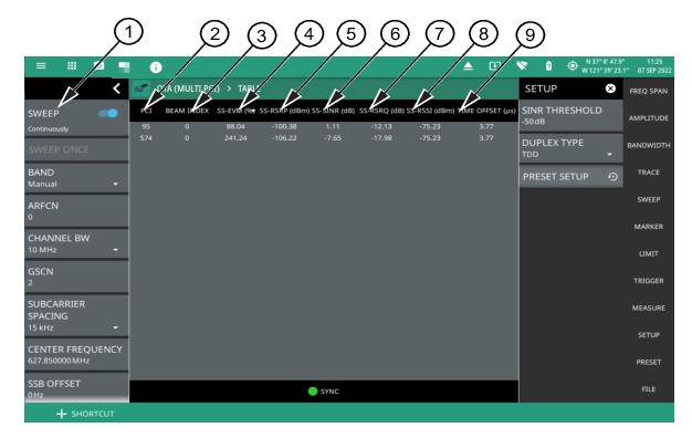
OTA (Multi PCI) Table View
The following measurement is set up to display 5GNR OTA (Multi PCI) data in a table view. The OTA (Multi PCI) table view displays the measurement results of every detected beam in a single, sortable table.
5GNR OTA (Multi PCI) – Table View
1. 5GNR Analyzer Status Panel: Each measurement features a unique status panel that displays settings and information relevant to the current measurement and view settings. This panel provides quick access to the measurement frequency, subcarrier spacing, channel bandwidth, and band configuration. See Status Panel (5GNR Summary).
2. PCI: These fields show the physical-layer cell ID value. The values can be sorted in ascending or descending order by tapping the column head.
3. BEAM INDEX: These fields show the beam index value of the corresponding physical-layer cell ID.
4. SS-EVM (%): These fields show the error vector magnitude values of the corresponding physical-layer cell ID and beam index, measured in percentage.
5. SS-RSRP (dBm): These fields show the secondary synchronization signal reference signal received power of the corresponding physical-layer cell ID and beam index, measured in dBm. The values can be sorted in ascending or descending order by tapping the column head.
6. SS-SINR (dBm):These fields show the secondary synchronization signal-to-noise and interference ratio of the corresponding physical-layer cell ID and beam index, measured in dB. The values can be sorted in ascending or descending order by tapping the column head.
7. SS-RSRQ (dB): These fields show the secondary synchronization signal reference signal received quality of the corresponding physical-layer cell ID and beam index, measured in dB.
8. SS-RSSI (dBm): These fields show the secondary synchronization signal reference signal strength indicator of the corresponding physical-layer cell ID and beam index, measured in dBm.
9. Time Offset (µs): Time difference between the measured start of the 5GNR frame and the 10 ms frame trigger, which is automatically synchronized to GNSS (GPS) when the instrument has GNSS (GPS) lock.
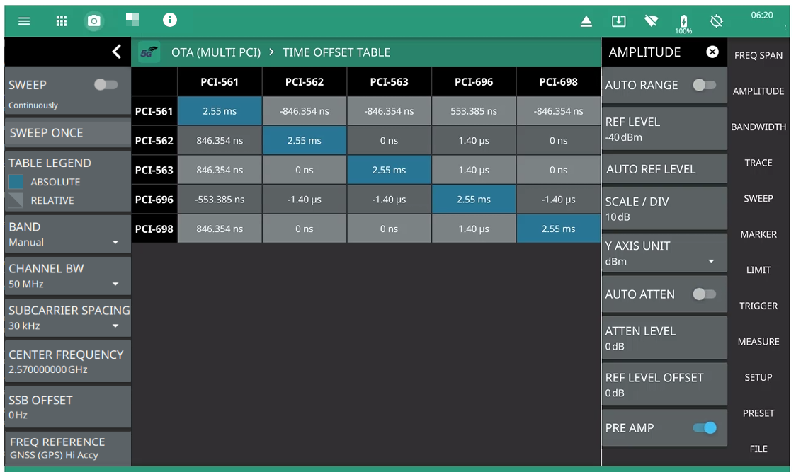
OTA (Multi PCI) Time Offset Table View
The following measurement is set up to display the time offset values in a table view. The OTA (Multi PCI) time offset table view displays the measurement results of every detected beam in a single, sortable table.
When measuring the 5G gNB over the air, it is likely that more than one gNB base station will be detected by the instrument. The time offset table shows the absolute time offset for the every detected PCI from all gNB base stations, as well as the relative time offset between any two PCIs.
Absolute time offset values are highlighted in blue colored cells whereas the relative time offset values are highlighted in gray colored cells. The table format is determined by the number of gNB PCIs detected in each measurement cycle.
The relative time offset value indicates the time offset between the two PCIs at a given location of the instrument.
5GNR OTA (Multi PCI) – Time Offset Table View
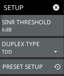
SETUP Menu (OTA (Multi PCI))
The 5GNR Summary and OTA (Multi PCI) SETUP menu is available in MEASURE > MEASUREMENT > OTA (Multi PCI) > SETUP.
5GNR SETUP Menu (5GNR Summary and Multi PCI)
-
SINR THRESHOLD
Sets the threshold level that the secondary synchronization signal-to-noise and interference ratio that a beam must overcome to be analyzed.
DUPLEX TYPE
Selects either frequency division duplex (FDD) or time division duplex (TDD).
PRESET SETUP
Presets the SETUP menu to default settings.
Status Panel (5GNR OTA (Multi PCI))
The status panel illustrated in this section is unique to the current analyzer and to the particular measurement and view that is selected. Figure: Status Panel (5GNR OTA (Multi PCI) Measurement) shows the 5GNR status panel that covers the 5GNR OTA (Multi PCI) measurements (selected via MEASURE> MEASUREMENTS menu).
Status Panel (5GNR OTA (Multi PCI) Measurement)
SWEEP: Toggles the current sweep setting between continuously or sweep once.
SWEEP ONCE
When sweep is set to single sweep, SWEEP ONCE updates the measurement display. Data continues to be captured in the background.
TABLE LEGEND
Displays only when TIME OFFSET TABLE is selected in 5GNR OTA (Multi PCI) mode. The absolute time offset values are shown in blue color and the relative values are shown in light and/or dark gray colors.
BAND
Select MANUAL, GLOBAL ALL or one of the predefined bands. Selecting MANUAL hides ARFCN and GSCN settings. Selecting a predefined band or GLOBAL ALL enables the ARFCN and GSCN settings.
REF LEVEL
The reference level is the top graticule line to the left on the measurement display.
SCALE/DIV
The scale can be set from 1 dB per division to 15 dB per division. The default setting is 10 dB. Selecting the plus (+) or minus (–) control changes the value by 1. SCALE/DIV is not available when linear y-axis amplitude units are selected.
ARFCN
ARFCN is the Absolute Radio Frequency Channel Number. The ARFCN is a unique identification number assigned to each radio channel within a communications spectrum. The ARFCN can be used to calculate the center frequency of the radio channel. The available input range is dependent on the selected band.
CHANNEL BW
Sets the measurement channel bandwidth. The available bandwidth settings depend on the selected band and bandwidth option installed in the instrument. Refer to “Options Settings” in Instrument Overview chapter of the user guide.
GSCN
GSCN is the Global Synchronization Raster Channel. The GSCN identifies the mapping of the synchronous signal block (SSB). The available input range is dependent on the selected band.
SUBCARRIER SPACING
Sets the subcarrier spacing. The available input range is dependent on the selected band.
CENTER FREQUENCY
When the band is set to MANUAL, sets the center frequency of the measurement channel. Changing the center frequency sets the band to MANUAL.
SSB OFFSET
SSB is the Synchronous Signal Block. The SSB Offset sets the frequency offset between the SSB and the overall resource block.
FREQ REFERENCE
Indicates the current frequency reference source of Internal, External, or GNSS (GPS) Hi Accuracy (requires GPS). The instrument automatically selects the frequency reference in the following order of priority: external, GPS, then the internal time base.