LTE demod summary measurement is the default measurement in LTE analyzer mode. To select demod summary measurement go to main menu and press MEASURE > MEASUREMENT >Demod Summary. LTE demod summary measurements are used for compliance testing of 3GPP LTE networks and can evaluate active antenna systems for dynamic physical layer attributes and received power levels of the transmitted signal.
The instrument can analyze a single physical-layer cell or multiple physical-layer cells at one time. The following considerations apply to each measurement.
Single PCI:
• Better for conducted measurements, directional antenna measurements, or if only one cell is present.
• Only one cell is reported. If multiple cells are present, the analysis may jump to different cells or not analyze any of the cells.
Multi PCI:
• Better sync in over the air field conditions.
• Multiple Cells can be reported and sorted on various measurement parameters.
LTE demodulation summary views present the same measurement parameters in both frequency division duplex (FDD) and time division duplex (TDD). FDD or TDD duplex type is selected using the SETUP Menu (LTE Demod Summary). This section illustrates several LTE FDD measurements using both single PCI and multi PCI analysis techniques.
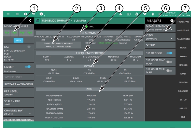
1. LTE Analyzer Status Panel: Each measurement features a unique status panel that displays settings and information relevant to the current measurement and view settings. This panel provides quick access to the MIMO antenna selection and status, sweep setting, and frequency and bandwidth configuration. See Status Panel (LTE Demod Summary).
2. MNC/MCC Info: This area shows the Mobile Network Code (MNC) and Mobile Country Code (MCC) codes along with the carrier and the country name. Touch this info to open SIB MEASUREMENT dialog. Note that the asterisk symbol on this information indicates the presence of LAST SIB DECODE info as shown in Figure: LTE SIB MEASUREMENT and LAST SIB DECODE.
3. PCI Summary: This area shows the physical cell ID, including the sector ID, cell group number, frequency error, time offset, sync status. Mobile Network Code (MNC) and Mobile Country Code (MCC). Sync status can indicate if there is a PSS or SSS failure, a Full Sync, or an Unknown condition. Also noted is the instrument’s reference clock accuracy of Internal, External, or GNSS (GPS) high accuracy (requires GPS).
4. Frequency Error: This section shows the frequency error of all the measured signals. It is the difference between the measured carrier frequency and the specified carrier frequency. This measurement is only as accurate as the frequency reference that is used and is typically only useful with a good external frequency reference or GNSS (GPS). It consists of the following data:
• Count: The total number of frequency measurements included in the averaging measurement.
• Average: The average value of all frequency measurements made.
• Standard Deviation: The measure of the spread of frequency measurements. The standard deviation is the average difference of all measurements from the average frequency measurement. Typically 68% of all measurements will fall within the standard deviation value shown.
• Minimum: The single lowest frequency value measured.
• Maximum: The single highest frequency value measured.
5. Power Summary: Shows the received power for each of the following:
• PBCH: Physical broadcast channel, the main purpose of which is to carry the broadcast information block.
• SS: Synchronization signal is used as a preamble sequence in LTE for synchronization purposes.
• RS: Reference signal is used as a pilot subcarrier for channel estimation and tracking in LTE.
• RS (0 through 3): Reference signal power of each of the MIMO antennas.
6. EVM Summary: Shows the RMS (%) of the error vectors between the reconstructed ideal signals and the received signals, divided by the RMS value of the ideal signals. The first column lists the average EVM (rms) value and the second column lists the peak measured value for each of the following as they are received:
• PBCH (QPSK): Physical broadcast channel, the main purpose of which is to carry the broadcast information block.
7. MEASURE Menu: To turn on SIB DECODE toggle from main menu access MEASURE menu.You can also customize the user map configuration and turn on SIB USER MNC/MCC MAP toggles by loading a preformatted carrier and country csv or txt file.
SIB Measurement
The MNC consists of either two or three decimal digits number used to uniquely identify a given network from within a specified country. Note that MNC of 001 is not the same as MNC of 01. Click on the MNC to view the SIB MEASUREMENT dialog that includes the System Information Block (SIB) and Master Block Information (MIB) data.
The MCC consists of three decimal digits excluding digits 1 and 8. The first digit of the mobile country code identifies the geographic region. Click on the MCC to view the SIB MEASUREMENT dialog that includes the System Information Block (SIB) and Master Block Information (MIB) data. Refer to LTE MIB/SIB Decode chapter for more information on the SIB measurement header sections tables and the corresponding fields, sub fields and their description.
In LTE MIBs and SIBs are used to carry different system information to customer premises equipment (CPE). The SIB messages are sent on PDSCH through RRC layer. SIB1 is carried under “SystemInformationBlockType 1” message name. Other SIBs (SIB2 to SIB11) are carried under “SystemInformation” message name and can contain multiple SIBs in the one message.
SIB1 is always sent in sub-frame #5 of the Radio-Frame, and continues retransmitting the same message in each 20 ms with different redundancy versions. Each 80ms a new SIB1 is transmitted.
The MIB message is broadcasted on PBCH. There is only one type of MIB. MIB is always sent in sub-frame #0 of the Radio-Frame, and continues retransmitting the same message in each 10 ms with different redundancy versions. Each 40ms a new MIB is transmitted.
Follow the steps below to view the SIB and MIB decodes:
• Press MEASURE menu and turn on SIB DECODE toggle. Notice the display of MNC and MCC information displayed in the PCI Summary section right below the PCI value. The SIB DECODE toggle is off by default because it may slightly slow down the measurement cycle time.
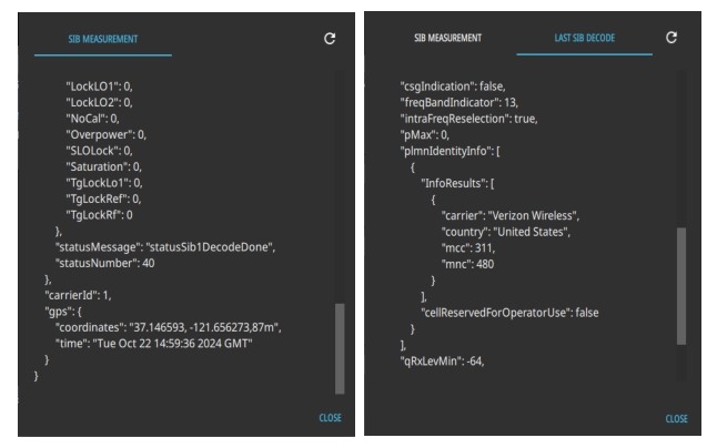
• Touch the MNC and MCC info area on the instrument display to open SIB MEASUREMENT dialog. Notice that you can still view the SIB Measurement dialog by touching the MNC and MCC info area even without any code being displayed. See Figure: LTE FDD Demod Summary Measurement.
• Scroll to the bottom of the SIB MEASUREMENT dialog to check the status message. If the status message is “statusSib1DecodeDone” and the “statusNumber” is 40, it indicates the instrument has successfully decoded MNC and MCC information.
• If the status message is “statusCoreset0Unavailable” it means that the SIB does not contain any MCC/MNC information to decode. This situation can legitimately occur if the cell site being tested is a supplementary link. In this case the mobile device would initially connect to a different band and the SIB1 information is provided by that band. For example, the LTE band could be from a non stand-alone network and the frequency band could be used to inform the mobile device of the MCC/MNC. See Anritsu Hardware Status for descriptions on the status messages.
• Press CLOSE to close the SIB MEASUREMENT dialog.
Note
The Anritsu Remote and Report Tools (ARRT) PC application provides a few additional capabilities in the SIB Measurement dialog, such as COPY MIB, COPY SIB and COPY ALL, to save data on your computer. On the other hand, saving a setup file saves the MIB and SIB measurement data onto your instrument.
LTE SIB MEASUREMENT and LAST SIB DECODE
SIB USER MNC/MCC MAPS
The default MCC/MNC results displayed by the instrument use an ITU library. As new networks are licensed, or networks change ownership or branding, the library may become out of date. Users can create their own MCC/MNC map of network operator names to ensure the displayed results reflect the most recent friendly name for any given network.
Access SIB USER MNC/MCC MAP toggles from MEASURE menu.
Note that these toggles are only enabled when custom user configuration files are placed in the root directory (Internal) of the instrument’s memory, or onto an external memory such as an encrypted FIPS compliant USB memory device. The configuration files can be saved as either as.txt or .csv files.
When the user configuration files are not saved in the instrument a parse error message will be displayed in the notification bar and the map toggles cannot be turned on.
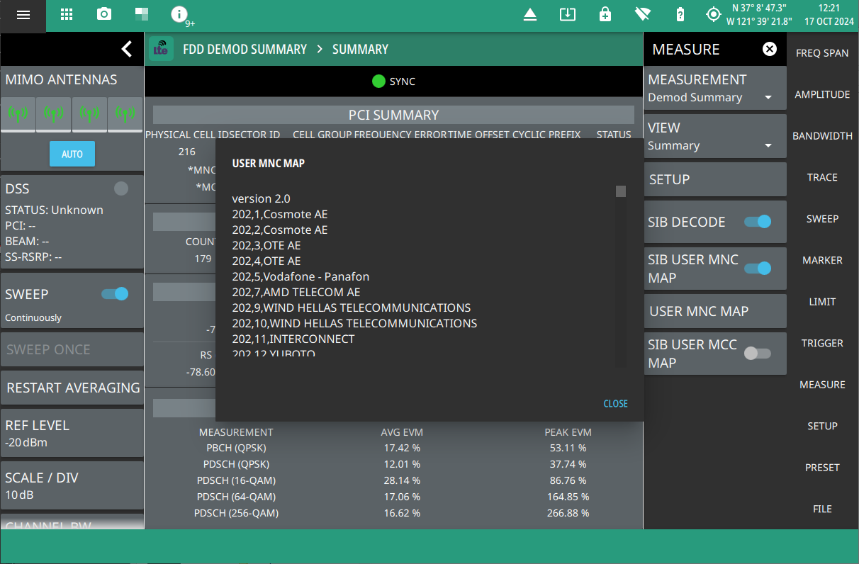
To view the USER MNC MAP dialog (see Figure: LTE USER MNC MAP) create a configuration file such as carriers.txt or carrier.csv and add the desired MNC, MCC codes and the corresponding carrier names and save the file either on a USB device or in the internal folder of your instrument.
The file contents must follow a specific format as explained below:
version <version code>
XXX,YYY,Carrier Name, wherein XXX represents the MNC and YYY represents the MCC.
For example,
version 1.0
260,1,T-Mobile / PTC S.A
Make sure to rename the version number for e.g. version 2.0 if new entries are added to the configuration files. This will allow you to invoke the recently updated configuration file.
LTE USER MNC MAP
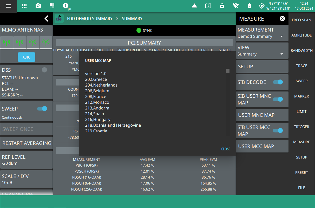
Similarly, to view USER MCC MAP dialog turn on SIB USER MNC MAP toggle under MEASURE menu. Create a configuration file such as “countries.txt” and add the desired MCC codes and the corresponding country names with the format as explained below:
The file contents must follow a specific format as explained below:
1. LTE Analyzer Status Panel: Each measurement features a unique status panel that displays settings and information relevant to the current measurement and view settings. This panel provides quick access to the MIMO antenna selection and status, sweep setting, and frequency and bandwidth configuration. See Status Panel (LTE Demod Summary).
2. MNC/MCC Info: This area shows the Mobile Network Code (MNC) and Mobile Country Code (MCC) codes along with the carrier and the country name. Touch this info to open SIB MEASUREMENT dialog. Note that the asterisk symbol on this information indicates the presence of LAST SIB DECODE info as shown in Figure: LTE SIB MEASUREMENT and LAST SIB DECODE.
3. PCI SUMMARY: This area shows the physical cell ID, including the sector ID, cell group number, frequency error, time offset, and sync status. Sync status can indicate if there is a PSS or SSS failure, a Full Sync, or an Unknown condition. Also noted is the instrument’s reference clock accuracy of Internal, External, or GNSS (GPS) high accuracy (requires GPS).
4. Time Alignment Error: Measures the delay between the signals from two antennas at the antenna ports.
5. Power and EVM: Measures the power of the reference and secondary sync signals, and the PBCH peak and RMS EVM. (EVM will only display for specific antenna combinations of {0}, {0,1}, {0,1,2,3}. All other combinations will display a blank EVM value.)
6. MEASURE MENU: Turn on SIB DECODE toggle to enable MCC and MNC info in PCI summary section.
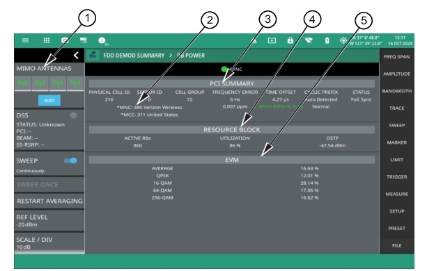
1. LTE Analyzer Status Panel: Each measurement features a unique status panel that displays settings and information relevant to the current measurement and view settings. This panel provides quick access to the MIMO antenna selection and status, sweep setting, and frequency and bandwidth configuration. See Status Panel (LTE Demod Summary).
2. MNC/MCC Info: This area shows the Mobile Network Code (MNC) and Mobile Country Code (MCC) codes along with the carrier and the country name. Touch this info to open SIB MEASUREMENT dialog. Note that the asterisk symbol on this information indicates the presence of LAST SIB DECODE info as shown in Figure: LTE SIB MEASUREMENT and LAST SIB DECODE.
3. PCI Summary: This area shows the physical cell ID, including the sector ID, cell group number, frequency error, time offset, and sync status. Sync status can indicate if there is a PSS or SSS failure, a Full Sync, or an Unknown condition. Also noted is the instrument’s reference clock accuracy of Internal, External, or GNSS (GPS) high accuracy (requires GPS).
4. Resource Block: Shows the number of active resource blocks, utilization (%), and the OFDM Symbol Transmit Power (OSTP) in dBm.
5. EVM: Shows the RMS (%) of the error vectors between the reconstructed ideal signals and the received signals, divided by the RMS value of the ideal signals for the average signal, QPSK, 16-QAM, 64-QAM, and 256-QAM.
LTE Summary Table View
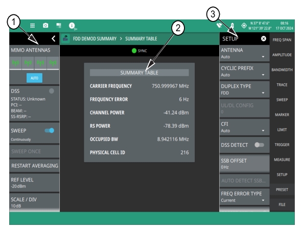
The LTE Demod summary table displays the measured values of carrier frequency which is calculated as the sum of center frequency and frequency error, channel power, RSRP power, occupied bandwidth and physical cell ID, as shown in Figure: LTE Demod Summary Table View.
LTE Demod Summary Table View
1. Status Panel: Each measurement features a unique status panel that displays settings and information relevant to the current measurement and view settings. This panel provides quick access to the measurement frequency, channel bandwidth, and Frequency Error Type. See Status Panel (LTE Demod Summary).
2. SUMMARY TABLE: This field indicates the current beam summary page.
• Carrier Frequency: The sum of center frequency and frequency error.
• Average Frequency Error: The average value of the frequency error of all the measurements. Frequency error is the difference between the received center frequency and the specified center frequency. This is tied to external frequency reference accuracy and is typically useful only with a good external frequency reference. To view current frequency error, select CURRENT from FREQ ERROR TYPE drop-down in the status panel/SETUP menu.
• Channel Power: The total power transmitted within a specified frequency or channel bandwidth.
• RS Power: The reference signal received power measured in dBm.
• Occupied BW: The bandwidth containing 99% of the total integrated power within the transmitted spectrum around the selected center frequency.
• Physical Cell ID: The physical-layer cell ID value.
3. SETUP MENU: Access SETUP menu to set the FREQ ERROR TYPE to either Current or Average. The demod summary measurement settings are configured in the SETUP menu refer to SETUP Menu (LTE Demod Summary).
SETUP Menu (LTE Demod Summary)
The SETUP menu is available in MEASURE > MEASUREMENT > Demod Summary > SETUP.
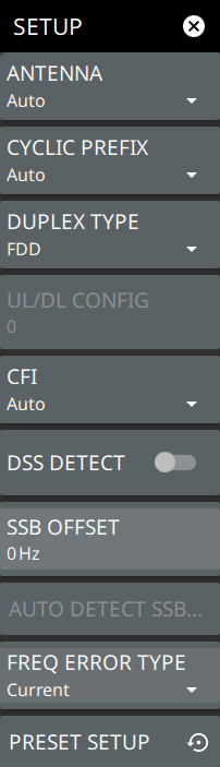
LTE SETUP Menu (LTE Demod Summary)
-
ANTENNA
Sets the MIMO antenna number (0 to 3, or AUTO) to use during a measurement. AUTO will use the antenna with the highest received signal power.
CYCLIC PREFIX
Sets the cyclic prefix (or guard time interval) to Normal, Extended, or Auto. The cyclic prefix is a duplication of a fraction of the symbol end. This setting affects the OFDM symbol sensitivity to time dispersion.
DUPLEX TYPE
Selects either frequency division duplex (FDD) or time division duplex (TDD).
UL/DL CONFIG
Available only in TDD duplex type. Sets the uplink/downlink (UL/DL) configuration, or Frame Format. This selection determines which sub-frames are uplink sub-frames and which are downlink sub-frames, and where the transitions between uplink and downlink sub-frames occur.
CFI
Selects the control format indicator (CFI) which indicates how many OFDM symbols are used for carrying the control channel at each sub-frame. CFI1 uses the first symbol at the sub-frame for PDCCH allocation. CFI2 uses the first and the second symbol for PDCCH. CFI3 uses the first three symbols for PDCCH.
DSS DETECT
Detects the Dynamic Spectrum Sharing (DSS) signal when turned On. This toggle only applies to FDD duplex type.
SSB OFFSET
SSB is the synchronous signal block. The SSB offset sets the frequency offset between the SSB and the center frequency of the channel. Negative values result in an offset lower than the center frequency. Positive values result in an offset higher than the center frequency.
AUTO DETECT SSB OFFSET
When DSS DETECT is toggled On, automatic detection of the SSB Offset is enabled.
FREQUENCY ERROR TYPE
Selects the frequency error type as either current or average. Shows the current frequency error value when CURRENT is selected. Shows the average of frequency error of all the measured channels. Note that this is only available in LTE Demod summary table view.
PRESET SETUP
Presets the SETUP menu to default settings.
Many operators are currently supporting 5G in existing sub 2.5 GHz bands using dynamic spectrum sharing (DSS). DSS technology allocates spectrum resources between LTE and 5G technologies in an LTE frame structure, and is often implemented with a software update to existing LTE radios and antennas. These network deployments usually implement traditional base station and antenna architectures with RF cable feeds between the two components. For this reason, tower crews must implement comprehensive RF cable testing during 5G network deployment and installation and maintenance (I&M).
Status Panel (LTE Demod Summary)
The status panel illustrated in this section is unique to the current analyzer and to the particular measurement and view that is selected.
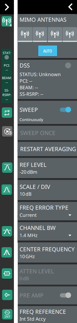
Status Panel with Minimized Icons (LTE Demod Summary Measurement)
MIMO ANTENNAS: Toggles the current MIMO antenna setting between AUTO or to select one of the available antennas. When a single antenna is selected, a blue underscore will appear below the antenna icon. The antenna icon is highlighted green when receiving a signal.
DSS: Displays the status of the detected DSS signal, in addition to PCI, BEAM, SS-RSRP values.
SWEEP: Toggles the current sweep setting between continuously or sweep once.
SWEEP ONCE
When sweep is set to single sweep, SWEEP ONCE updates the measurement display. Data continues to be captured in the background.
RESTART AVERAGING
Restarts the average frequency error value of the all the frequency measurements made.
REF LEVEL
Sets the reference level of the top graticule line in the selected units. If the reference level offset is not zero, OFFSET REF LEVEL is displayed at this location. Refer to Setting Amplitude.
SCALE/DIV
Sets the graticule scale/division for log-based units. This setting does not apply to linear units.
FREQUENCY ERROR TYPE
Selects the frequency error type as either current or average. Shows the current frequency error value when CURRENT is selected. Shows the average of frequency error of all the measured channels. Note that this is only available in LTE summary table view.
CHANNEL BW
Sets the measurement channel bandwidth.
CENTER FREQUENCY
Sets the center frequency of the measurement channel.
ATTEN LEVEL
When auto attenuation is off, sets input attenuation.
PRE AMP
Toggles the low-noise front-end preamplifier on or off. Refer to Setting Amplitude.
FREQ REFERENCE
Indicates the current frequency reference source of Internal, External, or GNSS (GPS) Hi Accuracy (requires GPS). The instrument automatically selects the frequency reference in the following order of priority: external, GNSS (GPS), then the internal time base.