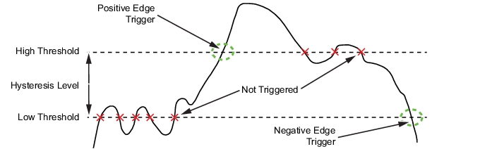
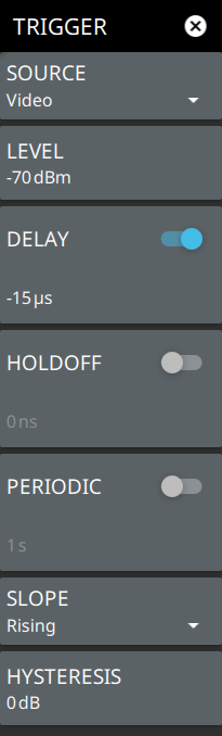
 | SOURCE The SOURCE button offers several triggering options depending on which view mode the instrument is set: • Free Run: A new sweep is started immediately upon completion of the current sweep. No trigger event is required to initiate a sweep. • Video: When enabled, the trigger level will be indicated graphically on the display with a horizontal VIDEO line. A new sweep is started when the input video level meets the value set via the LEVEL button. The level can also be adjusted by dragging the VIDEO line up or down. Video triggering is useful for monitoring a known time position and its transients, such as pulsed signal rise or fall times. • External 1 or 2: A TTL signal applied to the selected External Trigger MCX input connector causes a single sweep. After the sweep is complete, the resultant trace is continuously displayed until the next trigger signal is received. LEVEL Used when the trigger source is set to Video. Sets the video trigger level threshold that initiates a sweep. The level crossing applies to rising or falling edges. Use the hysteresis setting below to adjust the sensitivity of the trigger level. HOLDOFF Available only when the trigger source is set to External or Video. When toggled on, the analyzer waits the user defined amount of time to re-arm the trigger between trigger events. If a trigger event is received after the previous trigger, but before the holdoff time has elapsed, that trigger event will be ignored. PERIODIC Used to set a periodic sweep trigger. When toggled on, the instrument waits the set time to start a sweep. SLOPE Used when the trigger source is set to External or Video. Sets the trigger slope to rising or falling edge. HYSTERESIS Hysteresis is used to address noisy trigger signals. The hysteresis setting adjusts the sensitivity of the trigger system (the difference between the firing level and the arming level as shown in Figure: Trigger Levels and Hysteresis). A low hysteresis value sets the arming and firing levels close to each other, meaning a small signal change will cause a trigger. A large hysteresis value sets the arming and firing levels far apart, meaning a large signal change will be required to cause a trigger. |