The only interconnection required for GPIB operation is between the signal generator and the controller. This interconnection is via a standard GPIB cable. The Anritsu part number for such a cable is 2100-1, -2, or -4 (1, 2, or 4 meters in length).
GPIB Cable Length Restrictions
The GPIB can accommodate up to 15 instruments at any one time. To achieve design performance on the bus, proper timing and voltage level relationships must be maintained. If either the cable length between separate instruments or the cumulative cable length between all instruments is too long, the data and control lines cannot be driven properly and the system may fail to perform. Cable length restrictions are as follows:
• No more than 15 instruments may be installed on the bus.
• Total cumulative cable length (in meters) may not exceed two times the number of bus instruments or 20 meters—whichever is less.
Note
For low EMI applications, the GPIB cable should be a fully shielded type with well-grounded metal-shell connectors.
Setting the GPIB Address
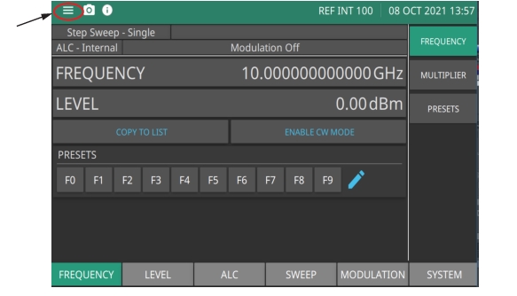
The default GPIB address is five. If a different GPIB address is desired, it can be accessed from the 3-line icon shown in Figure: System Configuration Menu.
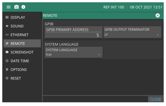
1. Press GPIB PRIMARY ADDRESS to change the current GPIB address of the signal generator.
2. Enter a new address using the cursor control keys or the data entry keypad and the terminator soft key The new GPIB address will now appear on the display. The entry range is between 1 and 30.
Selecting the GPIB OUTPUT TERMINATOR
Data is delimited on the GPIB by either the carriage return (CR) ASCII character or both the carriage return and line feed (CR/LF) ASCII characters. Which character is used depends upon the requirements of the system controller. Most modern controllers can use either CR, LF or CR/LF, while many older controllers require one or the other. The GPIB Output Terminator only applies to GPIB responses from the instrument. It is not linked with the command controller coming from the controller. Consult the controller's manual for its particular requirements.